Systems and methods for implementing a sample rate converter using hardware and software to maximize speed and flexibility

Active Publication Date: 2007-01-23
INTERSIL INC
View PDF11 Cites 121 Cited by
  • Summary
  • Abstract
  • Description
  • Claims
  • Application Information

AI Technical Summary

Benefits of technology

[0015]The use of both hardware and software components may provide a number of advantages over prior art systems. One potential advantage is that components for which processing speed is important may be implemented in dedicated hardware to maximize their performance, while other components for which flexibility is more important can be implemented in software. Another potential advantage is that hardware and/or software components may be common to (shared by) multiple channels, thereby reducing the c

Problems solved by technology

More particularly, these attempts utilized analog modulation schemes that resulted in very low performance applications.
These applications were very complex and costly to implement.
Consequently, these solutions were not widely accepted.
Prior art analog implementations of Class D technology have therefore been unable to displace legacy Class AB amplifiers in mainstream amplifier applications.
These digital PWM schemes, however, did little to offset the major barriers to integration of PWM modulators into the total amplifier solution.
Class D technology has therefore continued to be unable to displace legacy Class AB amplifiers in mainstream applications.
There are a number of problems with existing digital PWM modulation schemes.
One of the problems is that the performance and quality characteristics of the remainder of the signal processing system vary with the application.
As a result, implementation details cannot be accounted for

Method used


Image

  • Systems and methods for implementing a sample rate converter using hardware and software to maximize speed and flexibility
  • Systems and methods for implementing a sample rate converter using hardware and software to maximize speed and flexibility
  • Systems and methods for implementing a sample rate converter using hardware and software to maximize speed and flexibility

Examples


Example

[0021]While the invention is subject to various modifications and alternative forms, specific embodiments thereof are shown by way of example in the drawings and the accompanying detailed description. It should be understood, however, that the drawings and detailed description are not intended to limit the invention to the particular embodiment which is described. This disclosure is instead intended to cover all modifications, equivalents and alternatives falling within the scope of the present invention as defined by the appended claims.

DETAILED DESCRIPTION OF PREFERRED EMBODIMENTS

[0022]One or more embodiments of the invention are described below. It should be noted that these and any other embodiments described below are exemplary and are intended to be illustrative of the invention rather than limiting.

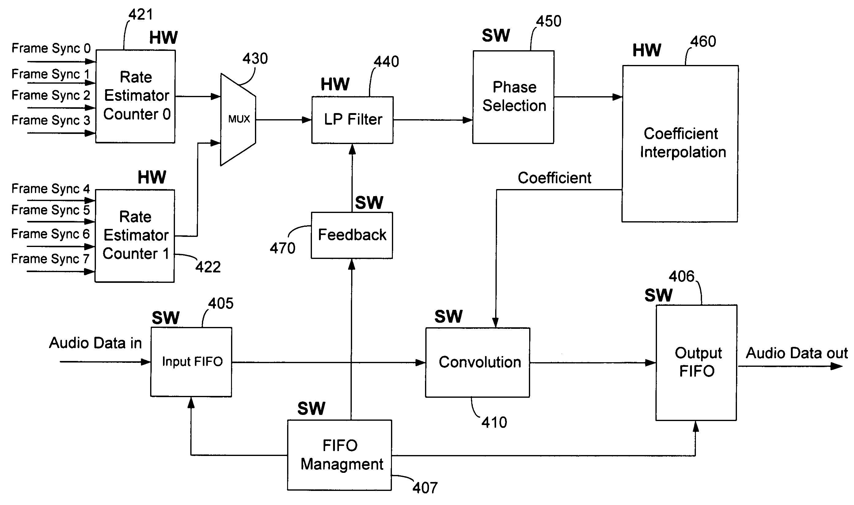
[0023]As described herein, various embodiments of the invention comprise systems and methods for converting a digital input data stream from a first sample rate to a second sample ...


PUM


Abstract

Systems and methods for converting a digital input data stream from a first sample rate to a second, fixed sample rate using a combination of hardware and software components. In one embodiment, a system includes a rate estimator configured to estimate the sample rate of an input data stream, a phase selection unit configured to select a phase for interpolation of a set of polyphase filter coefficients based on the estimated sample rate, a coefficient interpolator configured to interpolate the filter coefficients based on the selected phase, and a convolution unit configured to convolve the interpolated filter coefficients with samples of the input data stream to produce samples of a re-sampled output data stream. One or more hardware or software components are shared between multiple channels that can process data streams having independently variable sample rates.

Description

RELATED APPLICATIONS[0001]This application claims priority to: U.S. Provisional Patent Application No. 60 / 469,761, entitled “Systems and Methods for Implementing a Sample Rate Converter Using Hardware and Software to Maximize Speed and Flexibility,” by Andersen, et al., filed May 12, 2003; U.S. Provisional Patent Application No. 60 / 456,414, entitled “Adaptive Anti-Clipping Protection,” by Taylor, et al., filed Mar. 21, 2003; U.S. Provisional Patent Application No. 60 / 456,430, entitled “Frequency Response Correction,” by Taylor, et al., filed Mar. 21, 2003; U.S. Provisional Patent Application No. 60 / 456,429, entitled “High-Efficiency, High-Performance Sample Rate Converter,” by Andersen, et al., filed Mar. 21, 2003; U.S. Provisional Patent Application No. 60 / 456,421, entitled “Output Device Switch Timing Correction,” by Taylor, et al., filed Mar. 21, 2003; U.S. Provisional Patent Application No. 60 / 456,422, entitled “Output Filter, Phase / Timing Correction,” by Taylor, et al., filed M...

Claims


Application Information

Patent Timeline
IPC IPC(8): H03M7/00H03H17/06
CPCH03H17/0621H03H2218/06
Inventor ANDERSEN, JACK B.HAND, LARRY E.CHIENG, DANIEL L. W.PAGE, JOEL W.
Owner INTERSIL INC
Why Eureka
Try Eureka