Grating-based wavelength selective switch

a wavelength selective switch and wavelength-selective technology, applied in the field of wavelength selective switch technology, can solve the problems of difficult manufacturing, high packaging cost, limited current state of the art in wavelength selective optical switching based signal transmission system, etc., to achieve different optical propagation constants, reduce cross-talk, and increase the effect of signal coupling of optical transmission

Inactive Publication Date: 2007-01-23
INTEGRATED OPTICS COMM
View PDF3 Cites 22 Cited by
  • Summary
  • Abstract
  • Description
  • Claims
  • Application Information

AI Technical Summary

Benefits of technology

[0017]It is therefore an object of the present invention to provide new and improved methods and configurations for wavelength selective optical transmission system with coupling waveguides having wavelength selective Bragg gratings wherein the coupling waveguides are coupled based selection rules to reduce cross-talk between channels and to increase signal coupling of the optical transmissions between two waveguides. Specifically, the coupling waveguides are selected to have different optical propagation constant. In specific embodiments the coupling waveguides have different sizes and shape of cross sections. In another different embodiment, the coupling waveguides have different thickness to width ratios, i.e., different aspect ratios, to enhance the coupling of signals between the two adjacent waveguides.

Problems solved by technology

Current state of the art in wavelength-selective optical switching based signal transmission systems are still limited by several performance deficiencies caused by crosstalk, low coupling efficiency, and large size and poor form factors.
However, devices built using current TFF technology have the following disadvantages: they are difficult to manufacture when the channel spacing is below 200 GHz; the packaging cost is very high; and the yield is low.
Meanwhile, the disadvantages are that AWG devices are prone to cross talk and their packaging is complex.
However, the FBG products available in the current market have relatively high loss.
Moreover, each channel requires a circulator, which increases component costs and possibly increases packaging costs.
All the other technologies are still in the experimental stage and need years to become reliable enough for commercial applications.
On the other hand, these products and their methods of use are disadvantageous in the following aspects, First, in these switches, light travels through free space, which causes unbalanced power loss.
Secondly, in order to steer each mirror, three to four electrodes need to be connected to each mirror, which is a major challenge to produce large-scale mechanical-type MEMS-based switches.
Thirdly, alignment and packaging are difficult tasks particularly for large-scale switches.
The disadvantages are their questionable reliability and the excessive insertion loss for large-scale switches.
A common drawback of both of these MEMS-based switches is the requirement to work with external de-multiplexing and re-multiplexing devices in order to function properly in an optical networking system.
The requirements of implementing de-multiplexing and re-multiplexing functions add tremendous complexities to the system configuration and significantly increase the cost of manufacture, system installation, and maintenance of the optical network systems.
Another drawback is that these prior-art switching systems are not wavelength selective switches.
In another words, switching systems based on MEMS cannot selectively switch a particular wavelength from an input waveguide to a desired output waveguide.
In short, they are not wavelength intelligent devices.
However, since switching optical signals requires routing of the optical transmission, a wavelength-selective filter alone is not sufficient to build an optical switch.
One of the drawbacks of using circulators is that the circulators are expensive thus unduly increasing the implementation cost.
However, these patented technologies have technical limitations due to the interference of signal transmissions may occur when the wavelength of the reflected waves falls within the optical communication band as will be further explained below in FIG. 4.
As a result, performance degradation of the telecommunication networks is possible if not properly managed.

Method used


Image

  • Grating-based wavelength selective switch
  • Grating-based wavelength selective switch
  • Grating-based wavelength selective switch

Examples


case 1

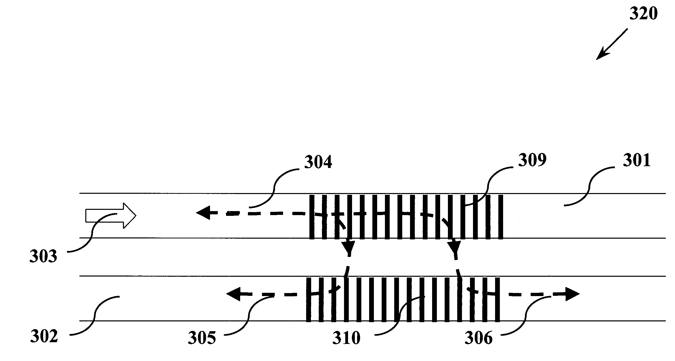
ation of the Contra-directional Coupling Signal 305 with β12

It should be noticed that in this case, from (3), (4) and (5) we have[0058](i) λR>λB1; and[0059](ii) λR>λBC.

As a result this case can be further subdivided into two sub-cases, as follows.

embodiment 1a

f the Contra-directional Coupling Signal 305 with β12 and λB1>λBC

If the window of wavelength is limited (within the desired range that are interested in) to between λmin and λmax, the grating period should be designed such that

λB1(max)min  (6)

In view of (5), this becomes

2β1Λmax<kλmin  (7)

On the other hand, according to (3)

kλmax=(β1+β2)Λmax  (8)

Combining (7) and (8), one obtains the selection rule for this case

[0060]λminλmax>2⁢β1β1+β2(9)

embodiment 1b

f the Contra-directional Coupling Signal 305 with β12 and λB1BC

Similar to the previous situation, in this case, it is required that

λBC(max)<λmin  (10)

Referring to (4), this means

(β2−β1)Λmaxmin  (11)

Combining (7) and (10), the selection rule for this case is given by

[0061]λminλmax>β2-β1β1+β2(12)

Thus, from (9) and (12) we obtained a general selection rule for Case 1 when β12

[0062]λminλmax>max⁡(2⁢β1β1+β2,β2-β1β1+β2)(13)


PUM


Abstract

The present invention is a wavelength-selective optical transmission system that includes a first waveguide for transmitting a multiplexed optical signal therethrough. The system further includes a second waveguide coupled to the first waveguide wherein a least one of the first and second waveguides have a set of wavelength-selective Bragg gratings disposed near a coupling section between the first and second waveguides to reflect a reflecting optical signal back to the first waveguide and for transmitting a contra-directional optical signal and a co-directional optical signal having respectively a contra-directional selected wavelength and a co-directional selected wavelength corresponding to the Bragg gratings. One of the contra-directional and co-directional wavelengths is chosen as a designated wavelength, and the reflecting optical signal and one of the contra-directional or co-directional optical signals are outside of a predefined range surrounding the designated wavelength.

Description

[0001]This application claims priority to pending U.S. patent application entitled “IMPROVED GRATING-BASED WAVELENGTH SELECTIVE SWITCH” filed Dec. 9, 2003 by Ling et al. and accorded Ser. No. 10 / 731,297 the benefit of its filing date being hereby claimed under Title 35 of the United States Code.BACKGROUND OF THE INVENTION[0002]1. Field of the Invention[0003]This invention relates generally to technologies for switching and routing optical wavelengths. More particularly, this invention relates to innovative method, structures and processes to manufacture and design improved waveguide grating-based wavelength selective switches.[0004]2. Description of the Related Art[0005]Current state of the art in wavelength-selective optical switching based signal transmission systems are still limited by several performance deficiencies caused by crosstalk, low coupling efficiency, and large size and poor form factors.[0006]Because of the extremely wide transmission bandwidth allowed by optical fi...

Claims


Application Information

Patent Timeline
Patent Type & Authority Patents(United States)
IPC IPC(8): G02B6/34
CPCG02B6/12007G02B6/124G02B6/125G02B2006/1215G02B6/29323G02B2006/12097G02B2006/12145G02B6/29319
Inventor LING, PEICHINGLUI, WAYNECHEN, JINLIANGZHANG, JIANJUNXU, MINGCHEN, YU
Owner INTEGRATED OPTICS COMM
Why Eureka
Try Eureka