Spectrometer using diffraction grating

a technology of spectrometer and grating, which is applied in the direction of spectrometry/spectrophotometry/monochromator, optical radiation measurement, instruments, etc., can solve the problems of large optical components such as diffraction gratings or lenses, large spectrometers, and high cost, and achieve high wavelength resolution power

Inactive Publication Date: 2007-01-30
NIPPON SHEET GLASS CO LTD +1
View PDF5 Cites 39 Cited by
  • Summary
  • Abstract
  • Description
  • Claims
  • Application Information

AI Technical Summary

Benefits of technology

[0010]In view of the above-noted problems, it is an object of the present invention to provide a spectrometer that has a high wavelength resolving power that can be made compact.

Problems solved by technology

The diffraction light rays generated by this periodic relief structure interfere with each other, so that light of certain specific wavelengths is emitted in specific directions.
However, making the optical components, such as the diffraction grating or lenses etc., larger leads to higher costs.
Therefore, there is also the problem that spectrometers tend to become large.

Method used


Image

  • Spectrometer using diffraction grating
  • Spectrometer using diffraction grating
  • Spectrometer using diffraction grating

Examples


embodiment 1

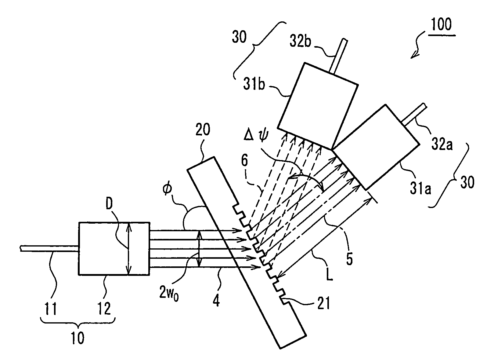
[0050]A spectrometer using a diffraction grating according to Embodiment 1 of the present invention is explained using FIG. 1. FIG. 1 is a diagram showing the configuration of a spectrometer 100 according to Embodiment 1 of the present invention. The spectrometer 100 of Embodiment 1 comprises a light-incident portion 10, a diffraction grating 20 and a light-emitting portion 30.

[0051]The light-incident portion 10 has an optical fiber 11, which is an incident-side optical waveguide, and a collimating lens 12, which converts a light beam into a substantially collimated light beam. The optical fiber 11 is a single-mode fiber (this includes polarization preserving fibers), and its numerical aperture is NA. The optical fiber 11 transmits light beams that include a plurality of wavelength components and approximate Gaussian beams. It should be noted that the NA is defined by the far field spread angle at which the intensity of the Gaussian beam is 1 / e2 of that at the center.

[0052]The colli...

embodiment 2

[0093]A spectrometer 200 using a diffraction grating 20 according to Embodiment 2 of the present invention is explained with reference to FIG. 4. FIG. 4 is a schematic diagram showing the configuration of the spectrometer 200 according to Embodiment 2 of the present invention. The spectrometer 200 of Embodiment 2 differs from the spectrometer 100 of Embodiment 1 with regard to the fact that it uses an optical fiber 11a that is a multi-mode fiber, instead of the single-mode optical fiber 11, but the remaining configuration is the same. Thus, identical members are denoted by identical numerals, and their further explanation has been omitted.

[0094]Since the optical fiber 11a at the light-incident portion 10 of Embodiment 2 is a multi-mode fiber, the light that is transmitted through and emitted from the optical fiber 11a can be regarded as light emitted from a planar light source (optical fiber 11a) having a uniform optical intensity. The conditions for minimization of the spectrometer...

embodiment 3

[0118]A spectrometer 300 using a diffraction grating according to Embodiment 3 of the present invention is explained with reference to FIG. 5. FIG. 5 is a schematic diagram showing the configuration of the spectrometer 300 according to Embodiment 3 of the present invention. The spectrometer 300 of Embodiment 3 differs from the spectrometer 100 of Embodiment 1 with regard to the fact that only one focusing lens33 used for all of the light beams of different wavelengths is provided. Emission-side optical fibers 34a and 34b are arranged at the outgoing end of the focusing lens 33. The spectrometer 300 of Embodiment 3 uses either the single-mode optical fiber 11 shown in Embodiment 1 or the multi-mode optical fiber 11a shown in Embodiment 2. The remaining configuration of the spectrometer 300 of Embodiment 3 is substantially the same as that of the spectrometer 100 of Embodiment 1. Therefore, identical members are denoted by identical numerals, and their further explanation has been omi...


PUM


Abstract

A spectrometer using a diffraction grating includes a light-incident portion including an incident-side optical waveguide emitting a light beam that includes a plurality of wavelength components and that approximates a Gaussian beam, and a collimating lens that is arranged on an emission side of the incident-side optical waveguide and that converts the light beam approximating a Gaussian beam that is emitted from the incident-side optical waveguide into a substantially collimated light beam; a diffraction grating having grooves on its surface, on which the light beam that has been converted into the substantially collimated light beam by the collimating lens is incident, the diffraction grating spectrally separating the light beam by emitting light beams whose emission direction depends on their wavelength; and a light-emitting portion having a plurality of focusing lenses that respectively condense the light beams that have been spectrally separated by the diffraction grating.

Description

TECHNICAL FIELD[0001]The present invention relates to spectrometers using a diffraction grating, which separate light of different wavelengths.BACKGROUND ART[0002]In recent years, the rapidly growing popularity of the Internet has caused a strong need for an increased information transmission capacity of optical fiber communication networks, and as a means to this end, the development of wavelength-division multiplexing (WDM) has advanced rapidly. In optical communication by wavelength-division multiplexing, light beams with slight wavelength differences transmit information separately, so that it is necessary to use such optical functional elements as spectral separators, filters and isolators having high wavelength selectivity. What is required of these functional elements is suitability for mass production, compactness, high integration and stability.[0003]Spectrometers are used to separate and detect optical signals in which a plurality of wavelengths are multiplexed intentional...

Claims


Application Information

Patent Timeline
Patent Type & Authority Patents(United States)
IPC IPC(8): G01J3/18G02B6/34G01J3/24G01R31/28G02B5/18G06F11/22
CPCG01J3/18G02B6/29311G02B5/1866G01J3/1804G01J3/0208G01J3/0218G01J3/24
Inventor NISHII, JUNJINAKAZAWA, TATSUHIROKITTAKA, SHIGEOTSUNETOMO, KEIJIOYA, KAZUAKI
Owner NIPPON SHEET GLASS CO LTD
Why Eureka
Try Eureka