Control apparatus for an internal combustion engine

a control apparatus and internal combustion engine technology, applied in the direction of electric control, combustion-air/fuel-air treatment, machines/engines, etc., can solve the problems of increasing calibration man-hours, exhaust gas deterioration, and inability to maintain the air fuel ratio, so as to reduce calibration man-hours and the memory capacity necessary

Active Publication Date: 2007-02-06
MITSUBISHI ELECTRIC CORP
View PDF11 Cites 17 Cited by
  • Summary
  • Abstract
  • Description
  • Claims
  • Application Information

AI Technical Summary

Benefits of technology

[0018]Accordingly, the object of the present invention is to obtain a control apparatus for an internal combustion engine which is capable of reducing calibration man-hours and the memory capacity necessary for a microcomputer by introducing a relatively simplified physical model of an internal combustion engine, of further eliminating, even under the state of transient operation, a devia

Problems solved by technology

That is, particularly, in case where the amount of purge air introduced changes greatly great, or where the amount of intake air changes greatly, there occurs a deviation in phase of the purge flow rate, the amount of intake air, and the amount of correction for the amount of fuel injected by the injector, so the air fuel ratio cannot be maintained to a target air fuel ratio (e.g., stoichiometric air fuel ratio), and, as a result, the exhaust gas is deteriorated.
Also, there are the following additional problems in the above-mentioned conventional apparatuses.
Since the amount of data required

Method used


Image

  • Control apparatus for an internal combustion engine
  • Control apparatus for an internal combustion engine
  • Control apparatus for an internal combustion engine

Examples


embodiment 1

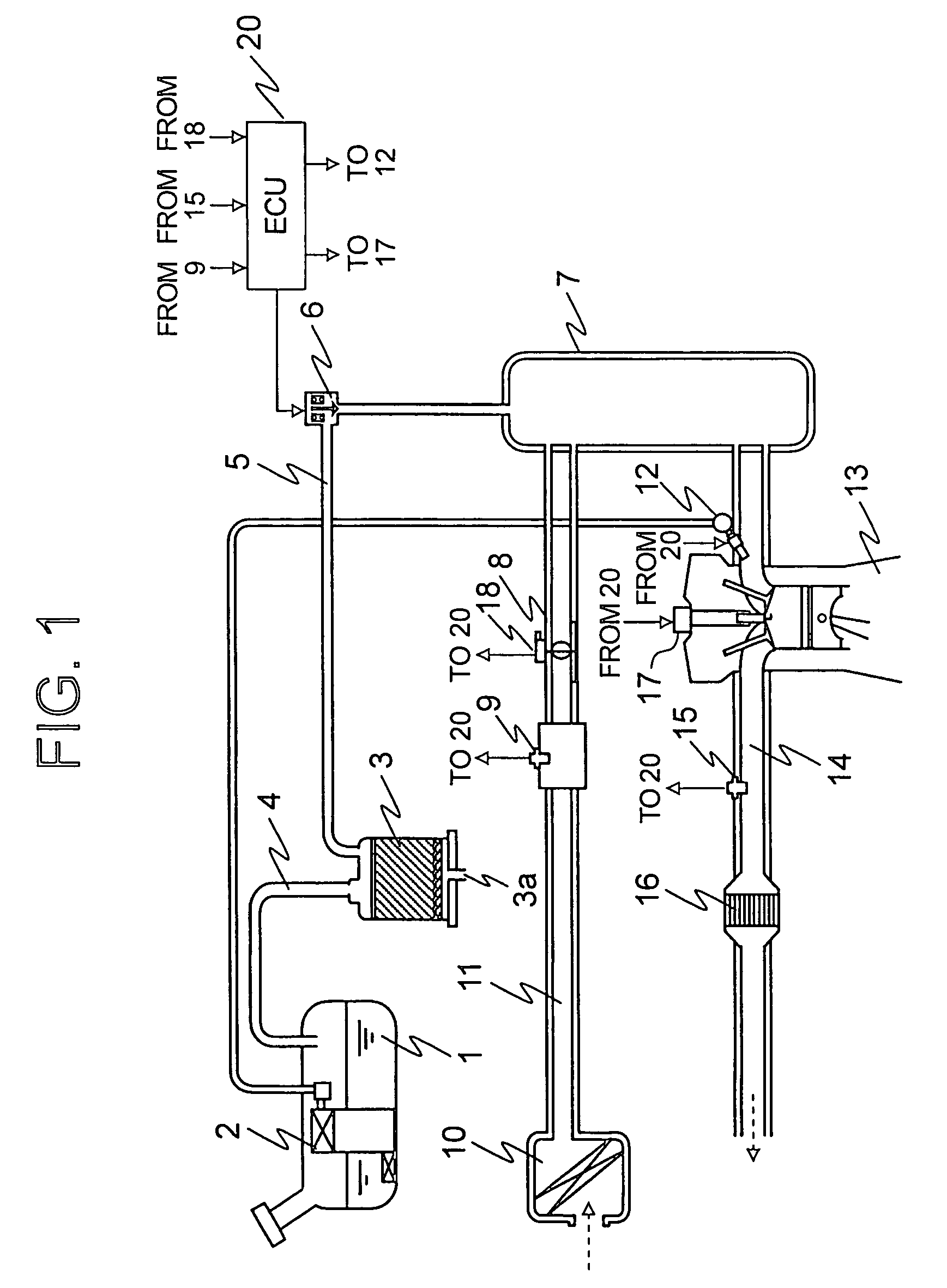
[0033]FIG. 1 is a construction view that conceptually shows a control apparatus for an internal combustion engine with an evaporated fuel treatment device according to a first embodiment of the present invention.

[0034]In FIG. 1, in a fuel tank 1 in which fuel is filled, there is arranged a fuel pump 2 that serves to supply the fuel to an injector 12 of an internal combustion engine 13. An upper portion in the fuel tank 1 is placed in communication with one end of a canister 3 through an evaporated fuel passage 4. The canister 3 has the other end thereof placed in communication with a surge tank 7 arranged in an intake system through a purge passage 5, in which a purge control valve 6 is arranged.

[0035]In an intake passage 11 of the internal combustion engine 13, there are arranged the surge tank 7, a throttle valve 8, an air flow sensor 9 and the injector 12, with an air cleaner 10 being arranged at an upstream and of the intake passage 11. A throttle opening sensor 18 for detecting...

embodiment 2

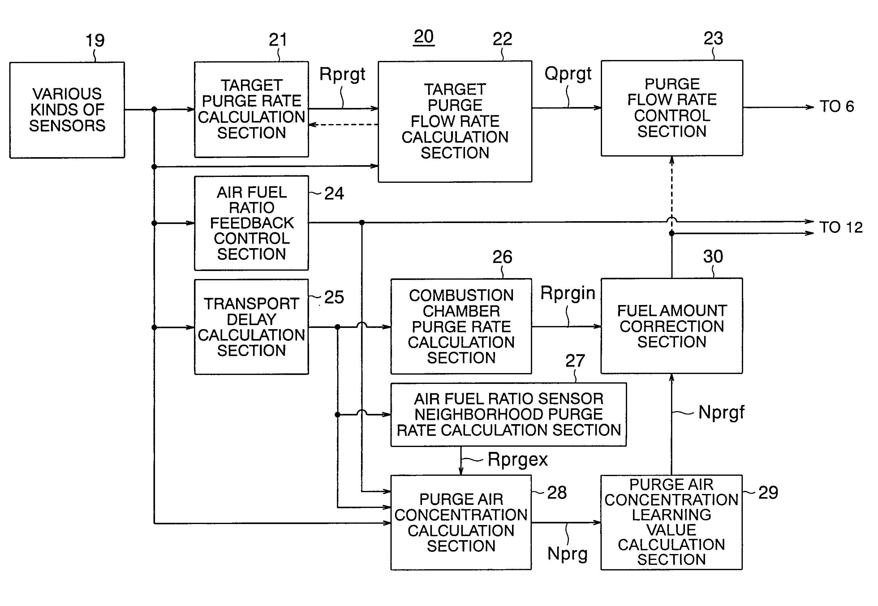
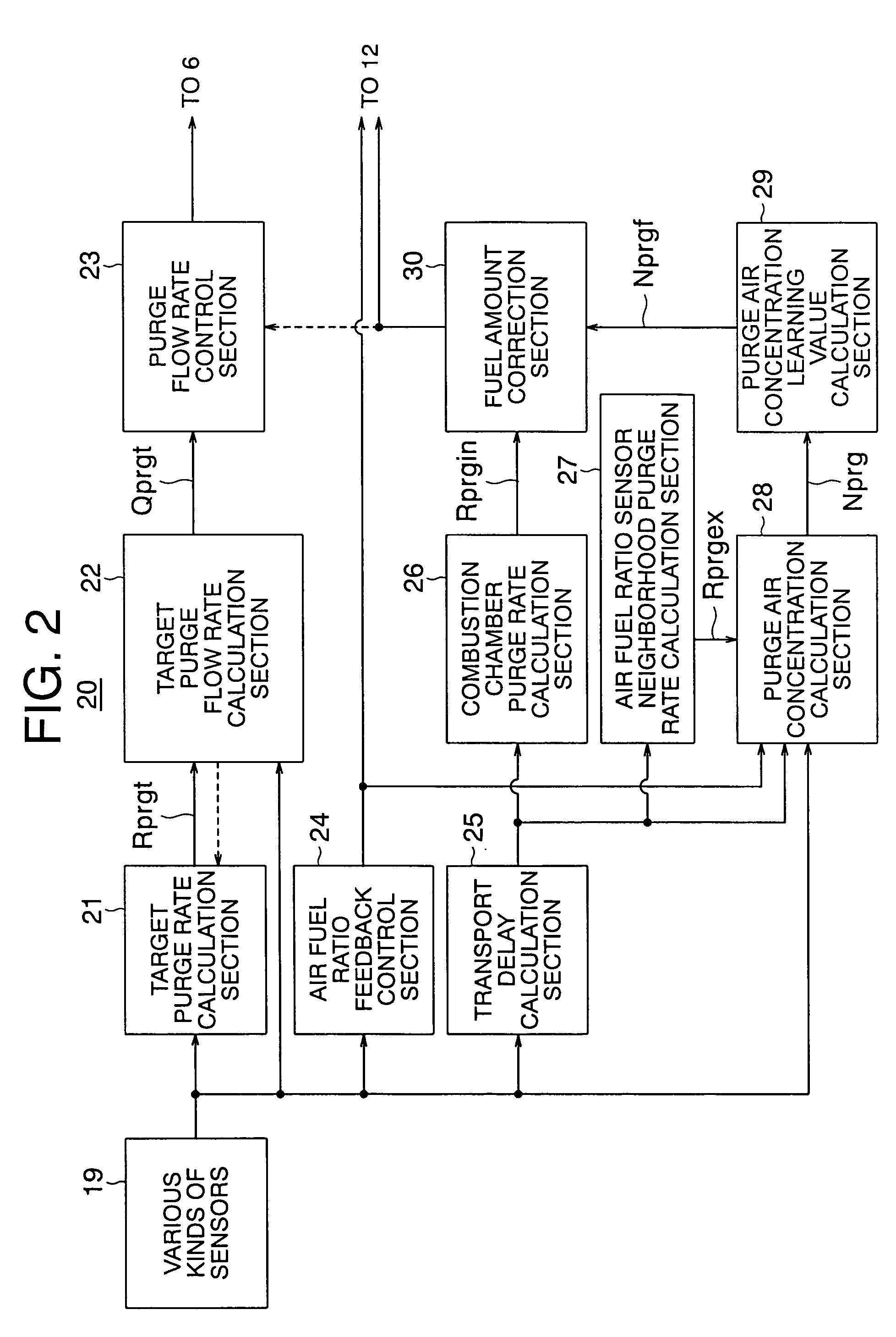
[0145]Though not particularly described in the above-mentioned first embodiment, an intake air amount decreasing correction section may be provided in the ECU 20 (see FIG. 1) for canceling out the amount of air contained in purge air.

[0146]In this case, the intake air amount decreasing correction section in the ECU 20 estimates the amount of air contained in purge air based on the purge flow rate controlled by the purge flow rate control section 23 and the purge air concentration Nprg calculated by the purge air concentration calculation section 28, and corrects the amount of intake air flowing from the throttle valve 8 or an ISC valve into the intake system by decreasing it by the amount of air that is contained in the purge air.

[0147]Specifically, a control apparatus for an internal combustion engine according to a second embodiment of the present invention includes, in addition to the functions of the above-mentioned first embodiment, an air amount calculation function to estimat...

embodiment 3

[0154]Though not particularly described in the above-mentioned first and second embodiments, a sonic nozzle (e.g., a Laval nozzle or also called a contraction and expansion tube) may be arranged in an internal passage of the purge control valve 6 used in the evaporated fuel treatment device, as shown in FIG. 10. FIG. 10 is a cross sectional view that shows the internal passage in the control valve 6 according to a third embodiment of the present invention, in which the construction unillustrated herein is similar to the corresponding one in the above-mentioned embodiments.

[0155]In FIG. 10, the purge control valve 6 has a structure using the sonic nozzle, with an orifice or restricted portion 62 being formed in a part of an internal passage 61. Here, the sonic nozzle will be described in some detail. By the provision of the restricted portion 62 in a part of the internal passage 61 for purge air, as shown in FIG. 10, when the internal pressure of the surge tank 7 (i.e., pressure in t...


PUM


Abstract

A control apparatus for an internal combustion engine prevents variation of an air fuel ratio even upon introduction of purge air. A delay time occurring until the intake air detected, after having arrived at the combustion chamber through a surge tank, influences an air fuel ratio sensor, a delay time occurring until purge air containing evaporated fuel generated upon purging a canister, after having arrived at the combustion chamber through the surge tank, influences the air fuel ratio sensor, and a delay time occurring until fuel supplied by an injector, after having arrived at the combustion chamber, influences the air fuel ratio sensor, are represented by simplified physical models. A purge rate in the combustion chamber or in the neighborhood of the air fuel ratio sensor is calculated by using the physical models, and a purge air concentration and a fuel correction amount are calculated based on the purge rate thus obtained.

Description

BACKGROUND OF THE INVENTION[0001]1. Field of the Invention[0002]The present invention relates to a control apparatus for an internal combustion engine that serves to temporarily store evaporated fuel generated in a fuel tank or the like into a canister (evaporated fuel adsorption device), and introduce it into an intake system of the internal combustion engine as purge air together with air. Also, the invention relates to a control apparatus for an internal combustion engine that serves to introduce evaporated fuel that leaked from a gap between a cylinder and a piston received therein of the internal combustion engine into an intake system thereof as a blowby gas together with air. More specifically, the invention relates to a control apparatus for an internal combustion engine capable of achieving excellent air fuel ratio control even in case a large amount of evaporated fuel is processed or treated.[0003]2. Description of the Related Art[0004]In the past, there has been known an ...

Claims


Application Information

Patent Timeline
IPC IPC(8): F02D41/14F02M33/04
CPCF02D41/0042F02M25/0827F02D41/0037F02D41/004F02D41/0045F02D41/06F02D41/12F02D41/1454F02D41/187F02D41/2454F02D2041/1431F02D41/10
Inventor HAGARI, HIDEKI
Owner MITSUBISHI ELECTRIC CORP
Why Eureka
Try Eureka