Systems and methods for defining a simulated interactive web page

a web page and interactive technology, applied in the field of systems and methods for defining interactive web pages, can solve the problems of not allowing much reflection or revision, affecting the quality of the application, and achieving the effect of facilitating the understanding of requirements, facilitating effective communication, and achieving higher quality requirements and irms

Inactive Publication Date: 2007-02-06
AXURE SOFTWARE SOLUTIONS
View PDF82 Cites 83 Cited by
  • Summary
  • Abstract
  • Description
  • Claims
  • Application Information

AI Technical Summary

Benefits of technology

[0046]Yet another advantageous feature of the present invention is the capability of the Studio software component, working in concert with the Music software component, to enable multiple users to collaboratively and simultaneously work on the same IRM. In the preferred embodiment of the present invention, several users may utilize individual copies of the Studio component on different computers, and in the context of the present invention each individual copy is referred to as an “instance” of the Studio. Modifications to the IRM made by one user working with that user's instance of the Studio are seen by other users working with their instances of the Studio on a near real-time basis. Furthermore, these changes are immediately visible to any user who is executing the IRM. As would be evident to a person skilled in the art, this near real-time capability constitutes another advantage of the invention relative to computer systems in which users must publish the results of their work to other users or computer systems in which users must actively retrieve the results of others' work. For example, consider two users Jon and Stephen, working collaboratively and simultaneously on the creation of a single IRM. As Jon adds new primitives to the model using his instance of the Studio component, Stephen's instance of the Studio program displays the new primitives on a near real time basis. Unlike many known computer systems, Jon does not need to instruct his instance of the Studio to update Stephen's instance, nor does Stephen need to request the latest IRM from Jon's instance. As used herein the term collaboration, and its variations, refer to the shared creation of two or more individuals with complementary skills by their interacting to create a shared understanding of a proposed software application that none had previously possessed or could have created alone. The goal of collaboration is the creation of value resulting from interactions among the collaborators. Collaboration, as thus defined, and as enabled by the system and process of the present invention, enables near real-time access by all collaborators. Thus, in accordance with the principles of the present invention the IRM serves as both a model and as a guide or “road map” for identifying and reducing ambiguity that arises during creation of a proposed software application before it is coded or deployed.
[0047]Similarly, changes to the requirements made by the ION or Studio software components are reflected in all other instances of ION and the Studio. This dynamic sharing of requirements and IRM information facilitates effective communication between all users of the system and contributes to higher quality requirements and IRMs. Furthermore, this dynamic sharing of information, coupled with the feature of a single electronic record of the requirements and IRM of a particular subject application, reduces the need for users to maintain and reconcile multiple copies of the same information.
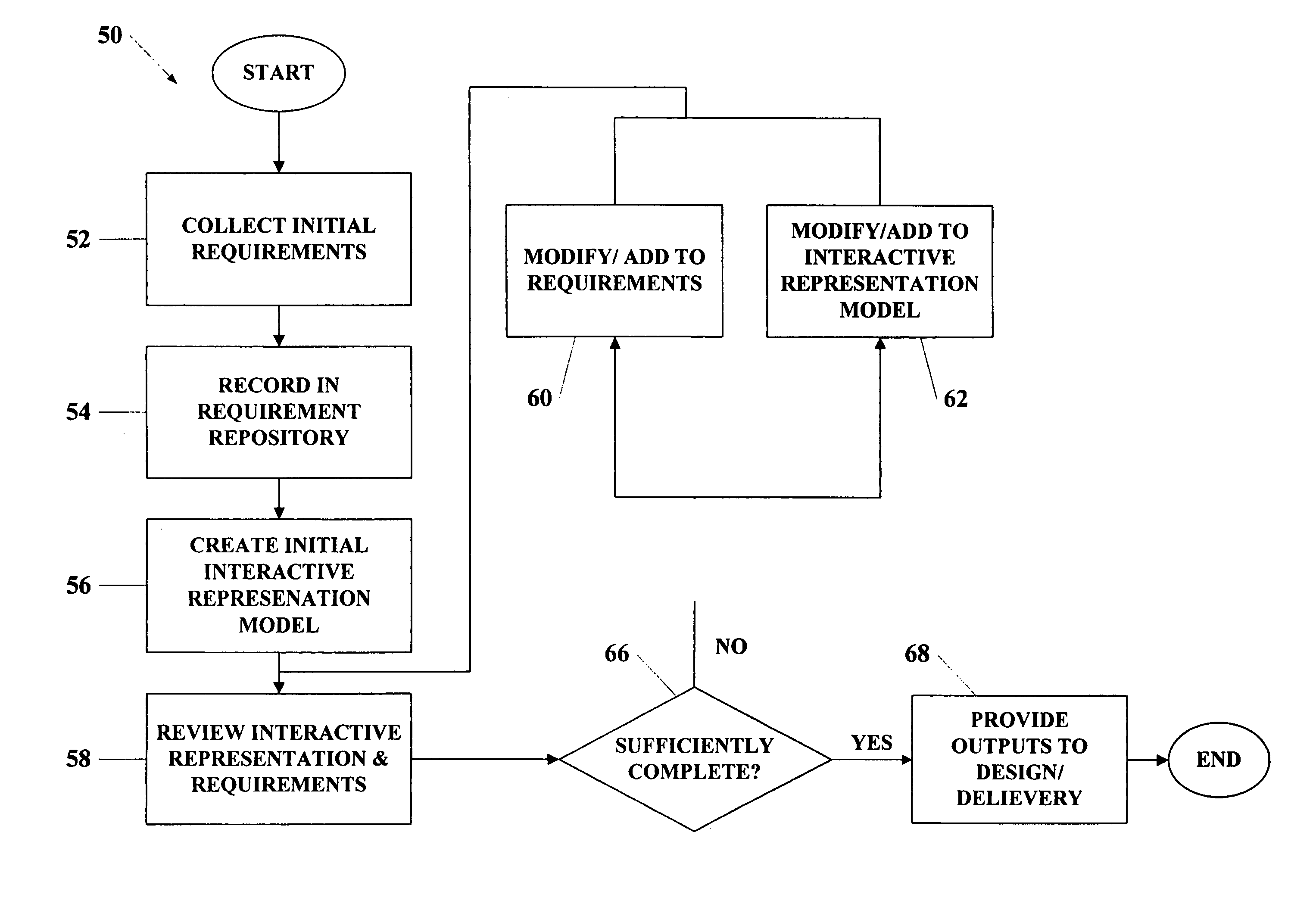
[0048]The next step in the overall process of the present invention is the review of interactive representation and requirements, shown at 58. In this step, the interactive representation of the subject application, in conjunction with the associated requirements, may be reviewed iteratively by business managers, business analysts, programmers, and proposed application users. In the presently most preferred embodiment or mode of practicing the invention, two activities are available for accomplishing this task: simulation and simulcasting, as will be described in detail below.
[0049]Simulation is an activity that begins when a user executes an interactive representation model by choosing the “simulate” menu item in the ION software component or the “simulate” menu item in the Studio software component. This choice causes the simulator component of the present invention to render the selected page of the IRM to the user's browser. As referred to in the present invention, the term simulator means a software component of the present invention that renders an interactive representation of a proposed application and related requirement information based on an interactive representation model and associated requirement information.
[0050]The simulator initially provides a list of the pages in the application to the user. The user then chooses the page at which they would like to simulate and calls the simulator again. Upon receiving the request for this page, the simulator creates a temporary memory area to build a response to the user's request. The simulator then “visits” the primitive that represents the page requested by the user and processes that primitive along with all of the primitives contained by that page. As it “visits” primitives, the simulator incrementally builds up its response. Some primitives are used to display variable data to users, and for each of these primitives, the simulator starts a separate process to determine the values of these variables. Once all the necessary primitives have been “visited” and their corresponding portion of the response has been appended to the response, the response is sent back to the user. Typically, the user then enters data and clicks on a button or link to submit this data for processing. The simulator receives this submission and extracts the values entered by the user into the fields that were presented to them. It then passes these values to primitives in the IRM that call standard sub-routines that process the data, and, in turn, pass the results of such processing on to other sub-routines for further processing. This continues until all processing is complete, at which point the simulator begins construction of the response to the user in the same way it constructed the user's first request for a page. Once completed, the simulator passes its response to the user, and waits for another request. This process repeats until the user has completed their interactive representation session.
[0051]Another advantageous feature of the present invention is its capability to display the requested page in a certain format referred to as “Meta” mode. In Meta mode the requirements associated to the primitives contained on the page through use of the Studio software component are displayed on the user's browser in addition to display of the page itself. Furthermore, each of the primitives that is visually represented on the page is automatically assigned a reference number, and each of the requirements displayed is cross referenced to these numbers. In the present invention, this display of the IRM page and the cross-referenced requirements is referred to as “requirements in context”. This feature of the present invention is intended to facilitate each user's understanding of the requirements and to significantly increase the likelihood of discovery of erroneous or incomplete requirements at this stage of the overall process. In addition, preferred embodiments of the present invention provide the capability to produce a report that contains the image of the page, the automatically assigned cross-reference numbers and the cross-referenced requirements.

Problems solved by technology

As organizations are forced to do more with less, the need to deliver such applications on-time and on-budget without sacrificing quality presents a bigger challenge than ever before.
One of the major problems in these fields is system definition, i.e., the effective identification of accurate, complete and unambiguous requirements for the system or application.
These applications must meet requirements related not only to graphic design, content and usability, but also related to complex scenarios of user system interactions that are not complete and accurate requirements from outset and may not even be documented before starting the application design.
Each of these approaches is associated with significant problems.
While waterfall development allows for departmentalization and managerial control, it does not allow for much reflection or revision.
However, once an application is in the testing stage, it is very difficult to go back and change something that was not well thought out in the concept stage.
Also, typically, problems are not discovered until system testing, and requirements must be fixed before the system is designed.
Requirements evolution makes the development method unstable.
Often during the design and code writing phases, requirements, inconsistencies, missing system components and unexpected development needs are discovered.
Also, system performance cannot be tested until the system is almost coded, and under-capacity may be difficult to correct.
For these reasons the standard waterfall model has been associated with the failure or cancellation of a number of large systems.
All of these waterfall type approaches suffer from the same or similar problems, however.
Because the requirements for most systems are not well understood in the beginning, the costs for development often become excessive and delivery schedules originally estimated must be revised.
Finally, because complex systems typically are not well understood in terms of their actual implemented behaviors, it is only through actual interaction with the system that the system designers and business analysts truly begin to understand what has been built.
Although the lessons learned may be valuable during waterfall implementations, they cannot easily be taken advantage of, due to the prohibitive costs of re-factoring the designs and implementations to reflect the new requirements that spring from these lessons.
The prototyping approach also has been associated with numerous problems, foremost among them is that prototypes are typically written in computer languages that only programmers can understand and use.
The first drawback is that business analysts, who are the people most likely to understand the needs and desires for the computer application, cannot develop the prototype without reliance on computer programmers, and must translate and communicate these needs and desires to computer programmers in order to have them construct the prototype.
This communication is traditionally inefficient and translation errors tend to be introduced because of the differences in the interpretation of the needs and desires for the prototype between two constituencies with differing backgrounds and skill sets.
Thirdly, programming resources need potentially expensive hardware and software tools to accomplish their work.
Fourthly, because prototypes are frequently constructed using the same infrastructure that the eventual application will be deployed upon, prototyping efforts are frequently delayed until strategic hardware acquisition, development software acquisition and training have been completed.
Yet another problem with prototyped systems is that they tend to become a replacement for actual development of the envisioned system.
Because the programmers were originally building just a subset of the system for demonstration purposes, short cuts typically are taken in this phase that lead to systems that do not scale well and have significant performance problems.
Yet another problem with coded prototypes is that they suffer from poor documentation, often because the prototype and the requirements are not represented within the same context.
Another problem with coded prototype based developments arises from the tendency for difficult problems to be pushed to the future, and not solved by the time of product completion, so that the initial hope of the prototype is not met by the subsequent product.
Prototypes created in this manner, however, suffer from additional drawbacks.
Foremost among them is that such static prototypes created with drawing and diagramming software are unable to convey to stakeholders an understanding of or how the application will behave.
To summarize the forgoing discussion of background art; coded prototypes suffer from drawbacks derived from the need to utilize computer programmers in their construction and static image prototypes suffer from drawbacks derived from the fact that they are inherently not interactive.
The reliance on static documents to transfer the requirements into a correct computer program results in repeated cycles of development.
These cyclic and redundant development activities inflate the cost of the resulting system.
This invariably leads to failures of the code to correctly embody the users' requirements, longer development cycles, increased costs and lower quality end products.
In addition, known computer application development approaches typically do not include input from all of the various stakeholders.
This serial process leads to misunderstandings, unresolved issues and misconceptions.
Finally, another problem with known software application development approaches is that software testers are provided with only a document for use in developing quality assurance and acceptance tests, and acceptance testing can occur only at the end of the development cycle.
This is an additional source of delay and problems because the quality assurance engineers are then required to conduct there own interpretation of all of the prior development work.

Method used


Image

  • Systems and methods for defining a simulated interactive web page
  • Systems and methods for defining a simulated interactive web page
  • Systems and methods for defining a simulated interactive web page

Examples


Embodiment Construction

Overview of Software Components and their Interaction

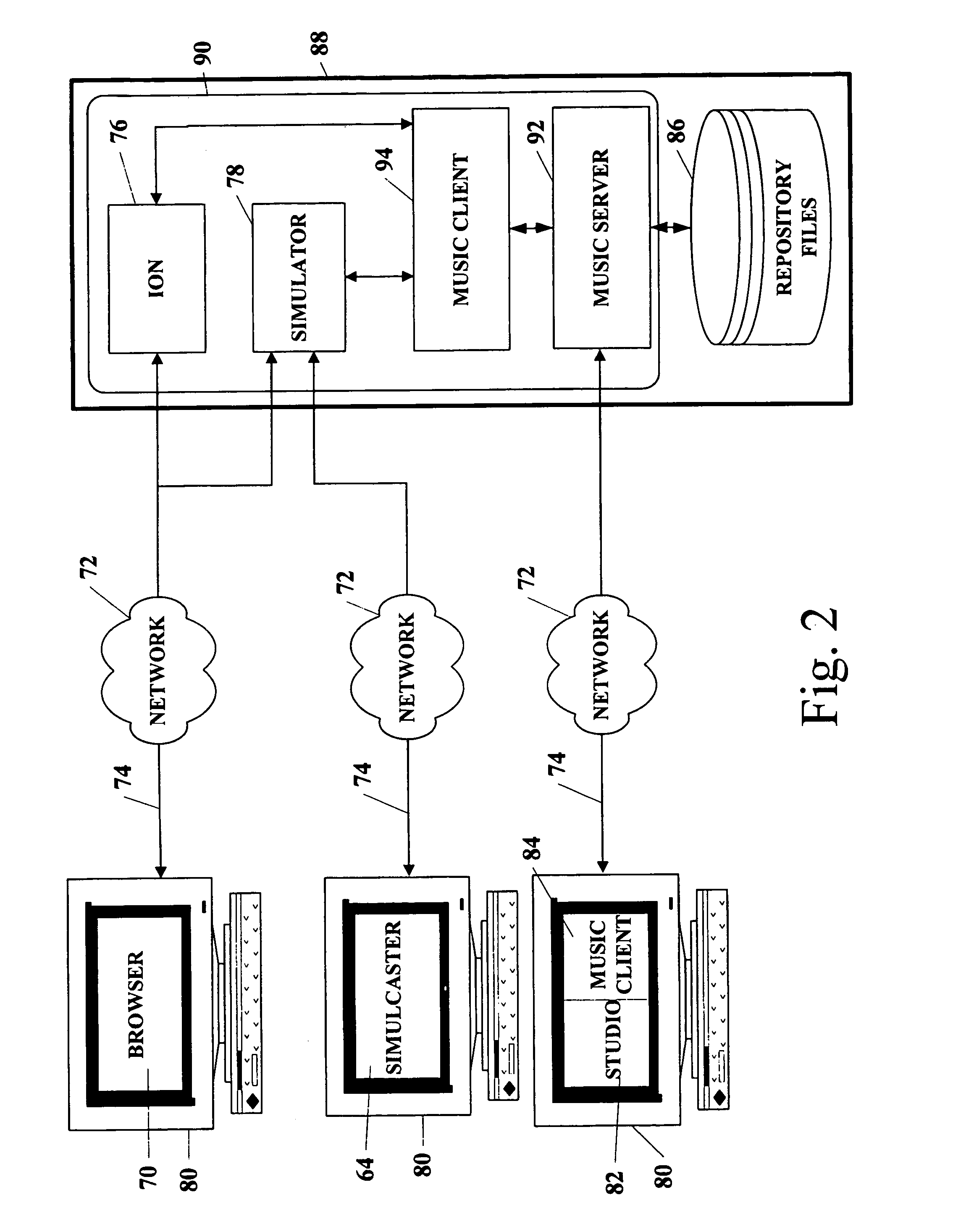
[0106]One preferred embodiment of the current invention includes several software components. These components and their interaction are described in this section, with reference to FIG. 2. The software components of the present invention may stored, individually or collectively on any computer-readable medium, such as, by way of example, including but not limited to conventional hard disks, CD-ROMS, Flash ROMS, nonvolatile ROM, RAM and floppy disks.

[0107]A standard browser (such as, preferably, Microsoft® Internet Explorer®70) is used to present the user interface of the ION component 76 of the present invention, as well as the user interface to the simulator component 78 of the present invention. The browser 70 and ION component 76 interact over a computer network 72 utilizing a TCP / IP and HTTP or HTTPS communication protocols 74. Similarly, the browser 70 and the simulator 78 interact over the computer network 72 utilizing TCP / ...


PUM


Abstract

The system includes a novel software application interactive representation modeling language, a software application (82) operative to use the modeling language to create, read and modify interactive representation models of the proposed applications, a memory (86) to store requirement data and interactive representation model data, a software application (92) operative to read and update the interactive representation model data across a computer network, a software application (76) operative to maintain a record of the requirements and to administer operation of the system, a software application (78) operative to render interactive representations of the proposed applications in browser readable format, a software application (82) operative to allow multiple instances of other applications to access interactive representation data and requirement data residing in the memory and a software application (84) operative to allow an individual user's interactions with the system to be broadcast across a networked system to other users.

Description

[0001]This application is a continuation application under 35 U.S.C. § 365(c) and 35 U.S.C. § 120 of prior PCT application PCT / US02 / 23816, filed Jul. 26, 2002, which was published as WO 03 / 010684 A1 on Feb. 6, 2003 under PCT Article 21(2) in English, which claims the benefit under 35 U.S.C. § 119(e) of U.S. Provisional Application No. 60 / 308,052, filed Jul. 26, 2001, the entireties of which are herein incorporated by reference.[0002]This application is related to (i) copending application entitled SYSTEM AND PROCESS FOR GATHERING, RECORDING AND VALIDATING REQUIREMENTS FOR COMPUTER APPLICATIONS, Ser. No. 10 / 484,541, which is the National Phase of prior PCT application PCT / US02 / 23816; to (ii) copending application entitled SYSTEMS AND METHODS FOR COLLABORATIVE PROGRAMMING OF SIMULATIONS OF COMPUTER PROGRAMS, Ser. No. 10 / 763,012, filed on the same date as the present application, which is also a continuation application of prior PCT application PCT / US02 / 23816; and to (iii) copending ap...

Claims


Application Information

Patent Timeline
Patent Type & Authority Patents(United States)
IPC IPC(8): G06F9/45G06F9/455G06F40/143
CPCG06F8/10G06F8/20G06F8/51G06F9/455G06F17/2247H04L12/1813G06F3/0484G06F3/04842Y10S707/99948Y10S707/99945G06F40/143
Inventor MARTIN, MAURICEBRICKLEY, STEPHENAMDOUR, LEONKRAVETS, ALEXFAN, BRIANINFANTE, DOMINICLARKING, STUARTALDAMA, PAUL
Owner AXURE SOFTWARE SOLUTIONS
Why Eureka
Try Eureka