

Methods and systems for groundwater remediation
a groundwater and remediation technology, applied in the field of groundwater remediation methods and systems, can solve the problems of significant health risks of human and animal populations at sites
- Summary
- Abstract
- Description
- Claims
- Application Information
AI Technical Summary
Benefits of technology
Problems solved by technology
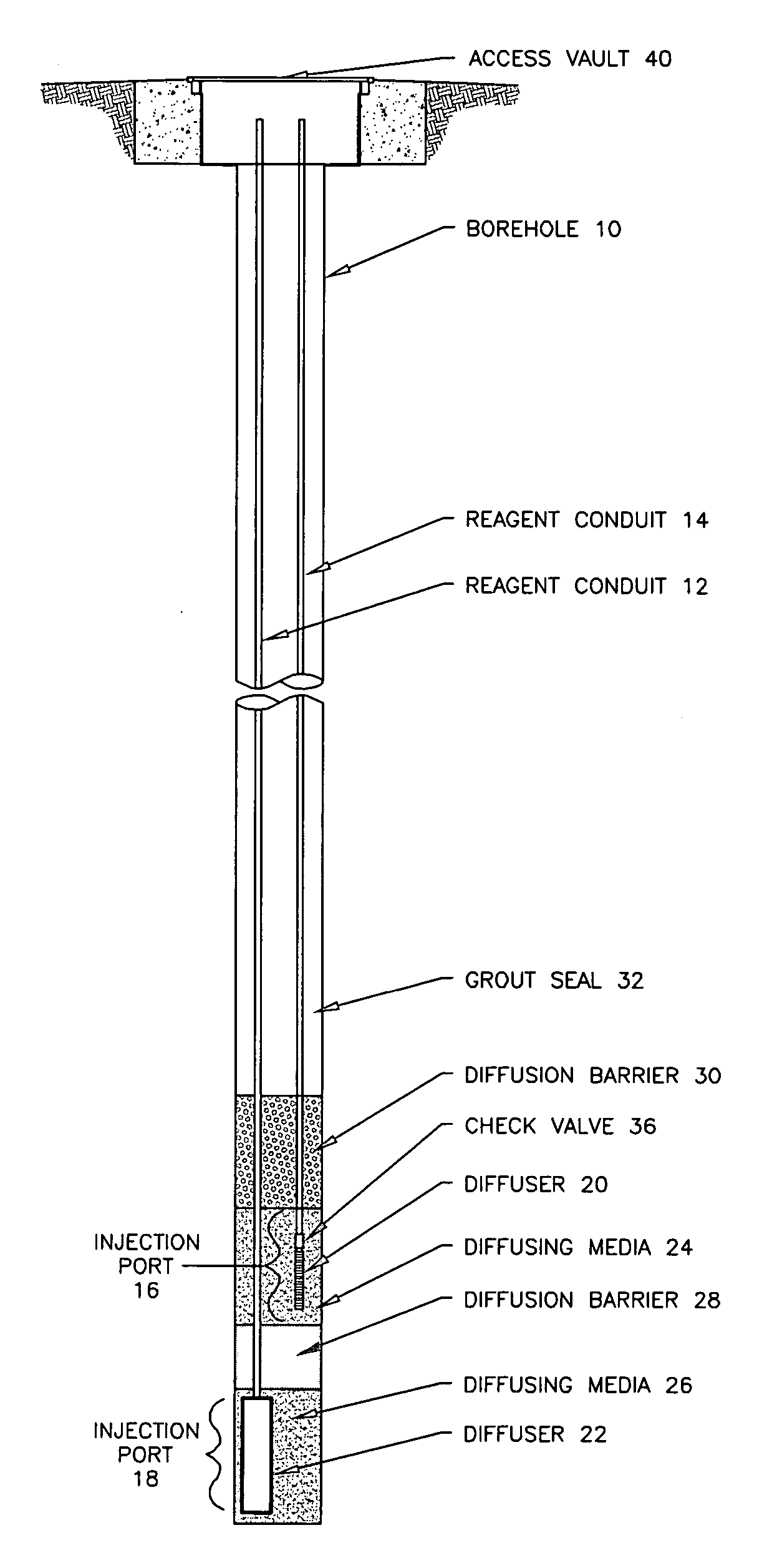
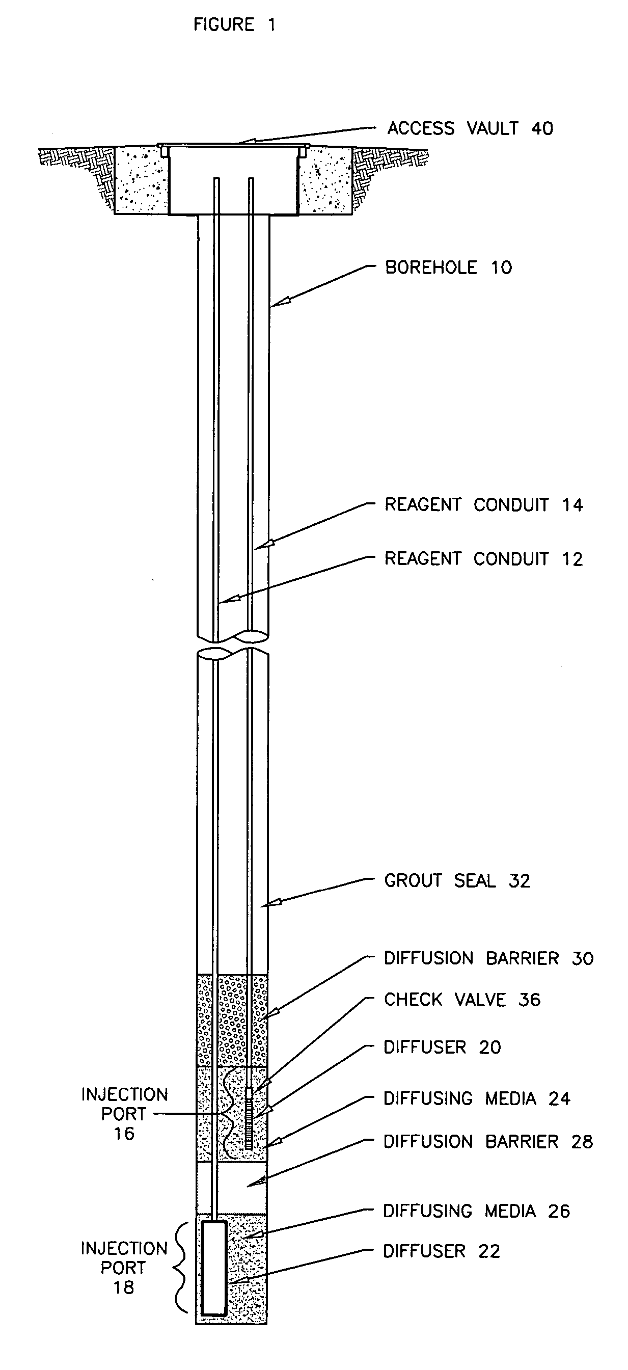
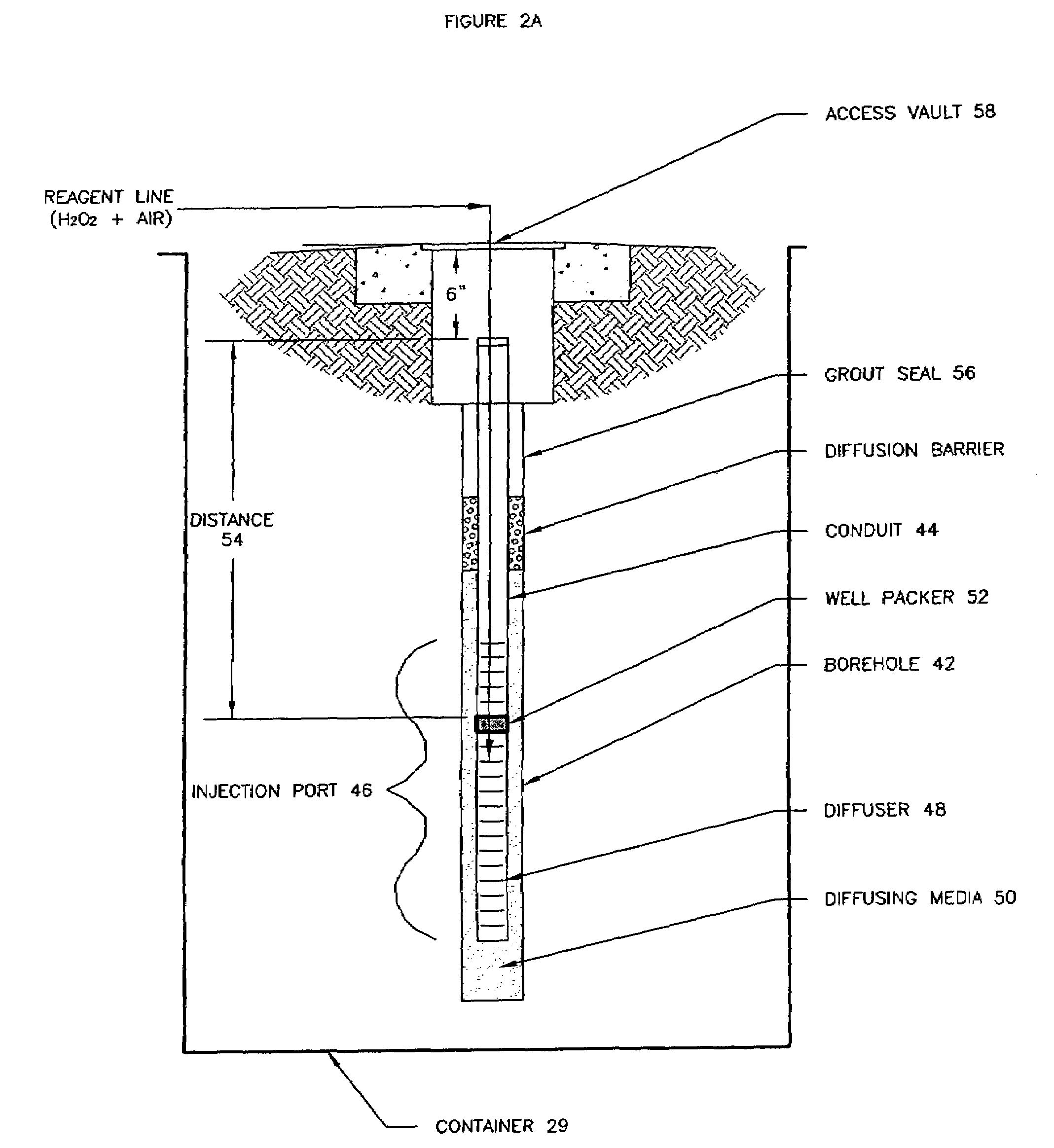
Method used
Image

Examples
example 1
Case Study
[0096]A combination of air / oxygen injection and chemical oxidation (via ozone / oxygen and hydrogen peroxide injection) remediation technologies in accordance with the invention were used to remediate a contaminated site, specifically, to reduce soil and groundwater concentrations of BTEX, MTBE, TBA, and TAME associated with a subsurface release of gasoline at the Country Store site on 11 Main Street in Kenton, Del.
Remediation System Overview
[0097]The chemical oxidation system activated fully following a five-day start-up period. Remedial system operation & maintenance (O&M) services were performed on a weekly basis.
Domestic Well Monitoring Results
[0098]Table 1 (FIG. 4a–e) summarizes the historical domestic well analytical data collected to date at the site. As shown on Table 1, concentrations of benzene, total xylenes, MTBE, TBA, and TAME were detected in the following domestic wells:
32 East Commerce Street—Old Domestic Well:
[0099]Benzene was detected at a concentration of ...
example 2
Case Study
[0125]Chemical oxidation remediation via hydrogen peroxide and air injection was performed at the Former Service Station #2-1279 in Fairview Village, Pa.
Nature and Extent of Hydrocarbon Presence / Site Geology:
[0126]The site is characterized by a shallow, unconfined aquifer consisting of approximately 5 to 15 feet of light brown silty and sandy clay with fragments of mudstone and shale overlying a two to three foot zone of semi-competent shale and competent shale bedrock. At the site, petroleum hydrocarbon compounds have been detected in soil and groundwater.
Monitoring Well Network:
[0127]Due to the varied construction details of monitoring wells and the occurrence of static water table levels in the unconsolidated material, at the soil-bedrock interface, and in the bedrock, the monitoring well network is separated into two networks: shallow well network and deep well network. The shallow well network is comprised of wells with total depths ranging from 8 feet to 20 feet bgs....
example 3
Case Study
[0150]Four two-day hydrogen peroxide and air injection events were conducted to remediate shallow dissolved toluene concentrations in a silty clay lithology. A total-phase vacuum extraction (TPVE) system had been operated for 3.5 years and successfully reduced the size of the plume and concentration levels, but did not achieve the clean-up goals.
[0151]Utilizing the methodology illustrated in FIG. 2B, a total of 7,000 gallons of 17.5% hydrogen peroxide solution were injected into a network of six existing monitoring and recovery wells. Compressed atmospheric air was injected at flow rates ranging from 5 scfm to 20 scfm at an applied pressure of 5 psi to 15 psi. The effective radius-of-influence without air injection was ten feet. With air injection, the radius-of-influence was 25 feet. As a result of the four injection events, the dissolved toluene concentrations were reduced by approximately 96% as shown in Table 8 below.
[0152]
TABLE 8Dissolved Toluene Concentrations (μg / L)...
PUM
 Abstract
Description
Claims
Application Information