
Method of producing a workpiece having at least one bearing eye

a technology of bearing eye and workpiece, which is applied in the direction of manufacturing tools, connecting rod bearings, reflex reflectors, etc., can solve the problems of unpredictable distribution of anti-friction coatings, insufficient adhesion between anti-friction coatings sprayed on and bearing eye surfaces, and high load requirements, so as to achieve low coating thickness, high fatigue strength, and thin anti-friction coatings.

Inactive Publication Date: 2007-02-20
MIBA GLEITLAGER GMBH
View PDF15 Cites 8 Cited by
  • Summary
  • Abstract
  • Description
  • Claims
  • Application Information

AI Technical Summary

Benefits of technology

[0003]The present invention is therefore based on the object of implementing a method of producing a workpiece forming at least one bearing eye of the type initially described in such a way that with a comparatively low production cost, high dynamic bearing load capacity may be ensured, as well as an advantageous service life.
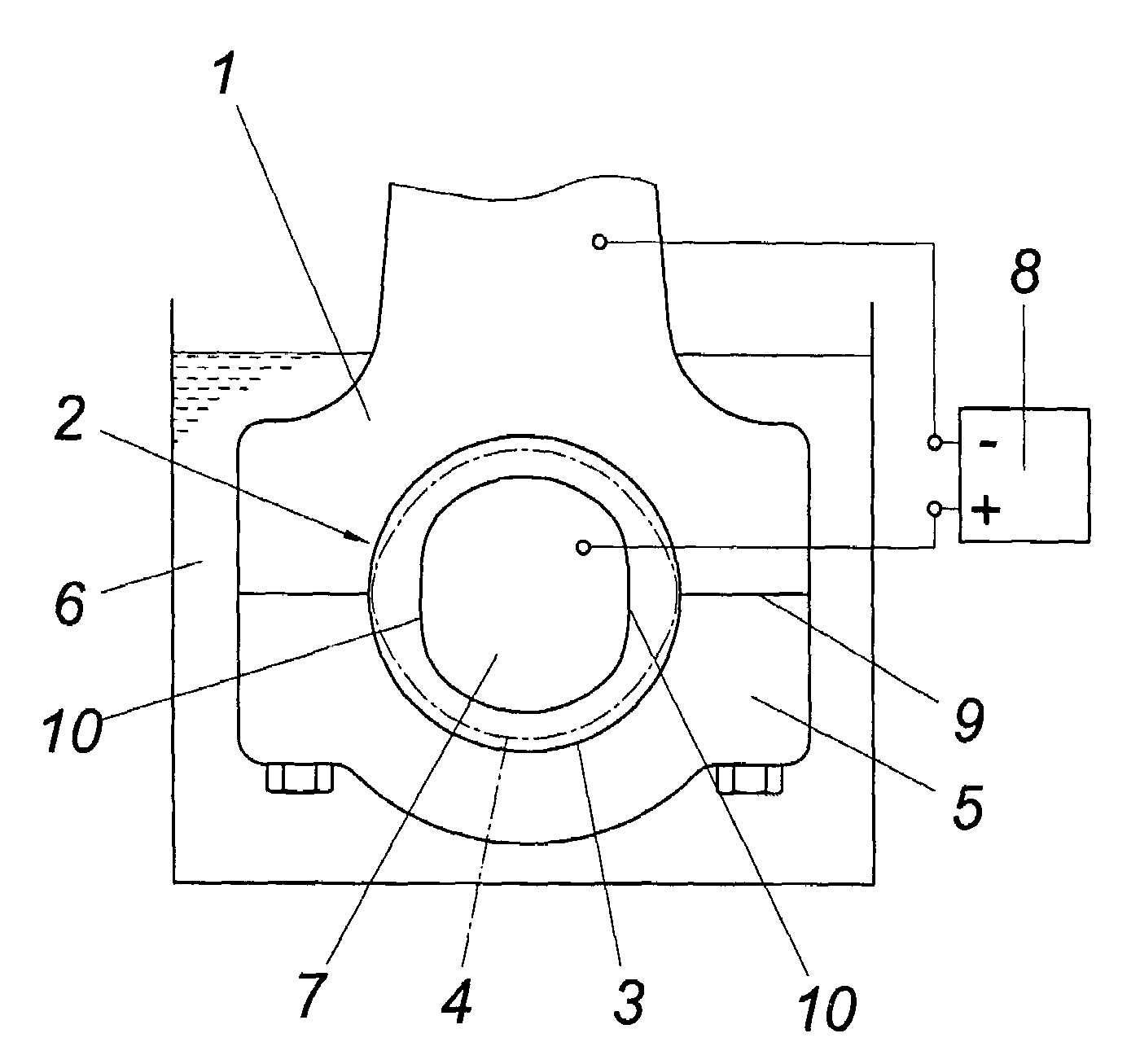
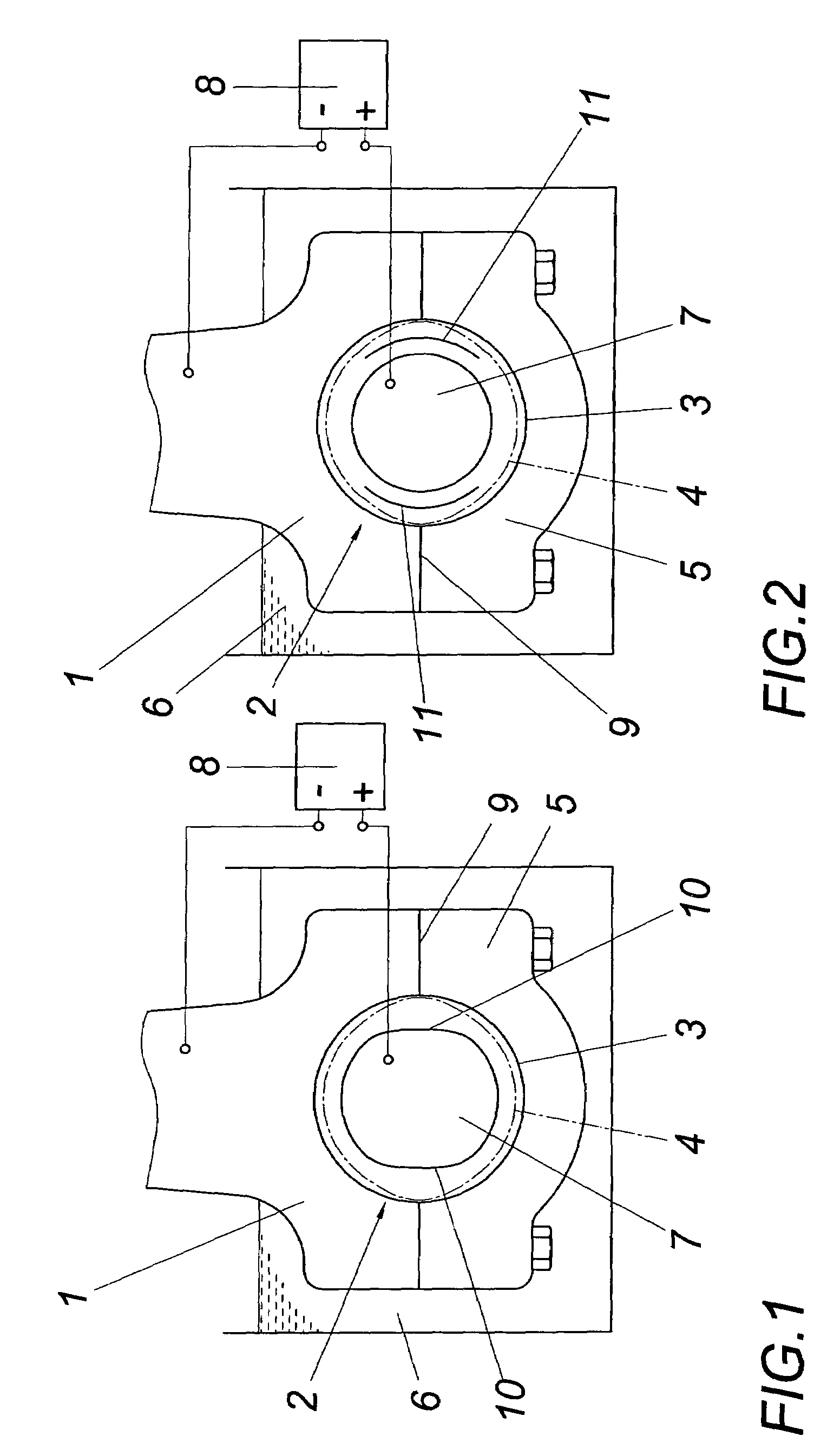
[0005]Since the bearing eye is processed for a precise fit to a circular cylinder before being coated, the final dimensions of the running surface formed by the anti-friction coating may be achieved through precise control of the application thickness of the anti-friction coating onto the processed bearing eye surface, without having to reprocess the running surface. The galvanic deposition of the anti-friction coating onto the processed bearing eye surface offers an advantageous possibility of applying the anti-friction coating onto the bearing eye surface using different depositing rates, because only a corresponding distribution of the electrical field over the bearing eye surface between an anode provided in the bearing eye and the material connected as a cathode must be ensured for this purpose. The depositing rate rises in the region of greater field strengths, so that if the depositing conditions are otherwise identical, the thickness gradient of the anti-friction coating deposited onto the bearing eye surface may be controlled very precisely via the field distribution. Therefore, for example, with a divided bearing eye, the release of the running surface often required in the region of the partition line may be achieved through a depositing rate for the anti-friction coating which is lower in the partition line region, with a comparatively thin anti-friction coating as a requirement for a high fatigue strength.
[0006]During the coating of a workpiece having a divided bearing eye, the bearing eye surface is processed for a precise fit after the divided bearing eye is assembled and then galvanically coated with the anti-friction coating before the anti-friction coating is divided by a fracture separation in accordance with the division of the bearing eye. Since the processing for a precise fit of the bearing eye surface is performed after the divided bearing eye is assembled, in order to provide the requirements for a tailored coating which ensures the final dimensions without reprocessing, after the anti-friction coating is applied in a thin layer, it must only be ensured that the anti-friction coating applied is divided in accordance with the division of the bearing eye, which is advantageously performed through a fracture separation. The comparatively low coating thickness and the good adhesion of the galvanically deposited anti-friction coating on the bearing eye surface represent advantageous conditions for fracture separation without problems.
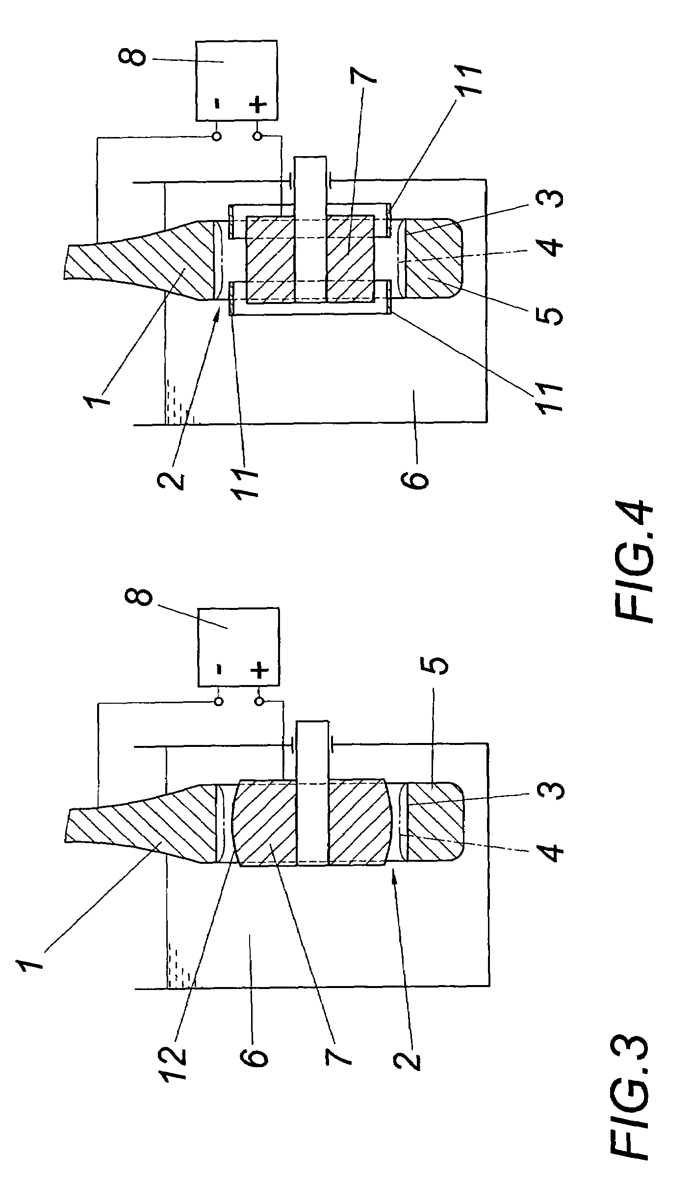
[0007]To produce workpieces according to the present invention having at least one bearing eye, on whose circular cylindrical bearing eye surface an anti-friction coating is deposited which forms a running surface deviating from a circular cylinder, it is possible to start from a typical device, which includes a device for galvanic deposition of the anti-friction coating on the bearing eye surface in an electrical field between the workpiece, which is connected as the cathode, and an anode coaxial to the bearing eye. To achieve a distribution of the electrical field over the bearing eye surface corresponding to the varying deposition rate required, the anode may have a shape deviating from a circular cylinder, having smaller radii in the depositing region of smaller coating thicknesses, so that in the region of the smaller coating thicknesses, there is a greater distance between the anode and the cathode surface formed by the circular cylindrical bearing eye surface. A comparable effect in regard to the field distribution over the bearing eye surface may be achieved if screens for the electrical field are provided in the annular gap between the bearing eye surface to be coated and the anode in the depositing region of smaller coating thicknesses.

Problems solved by technology

Such thermal spray methods have the disadvantage, however, that the adhesion between the anti-friction coating sprayed on and the bearing eye surface is not sufficient for high load requirements without something further.
In addition, due to the compensation of imprecisions, after the anti-friction coating has been processed for a precise fit, a non-uniform thickness of the anti-friction coating, whose distribution is unpredictable, must be expected.

Method used


Image

  • Method of producing a workpiece having at least one bearing eye
  • Method of producing a workpiece having at least one bearing eye
  • Method of producing a workpiece having at least one bearing eye

Examples


Embodiment Construction

[0013]In order to be able to coat a workpiece 1 having a bearing eye 2, such as a connecting rod, with an anti-friction coating 4 in the region of the bearing eye surface 3 in such a way that the running surface resulting from the anti-friction coating 4 does not require any reprocessing, the surface 3 of the bearing eye 2 is first processed for a precise fit to a circular cylinder. For a divided bearing eye 2, as is shown in the drawing, this means that upon a preferred fracture separation of the workpiece, the bearing eye 2 is first divided along an intended fracture point before the separated bearing cover 5 is attached again to process the bearing eye surface 3 in order to be able to compensate for deformations of the workpiece 1 during the fracture separation due to brittleness occurring in the region of the intended fracture point. After the processing of the running surface 3 for a precise fit corresponding to a circular cylinder, the workpiece 1 is prepared in a typical way ...


PUM

PropertyMeasurementUnit
thicknessaaaaaaaaaa
thicknessesaaaaaaaaaa
sizeaaaaaaaaaa

Abstract

A method of producing a workpiece (1) having at least one bearing eye (2) is described, the bearing eye (2) being coated with an anti-friction coating (4), which forms a running surface deviating from a circular cylinder. In order to provide advantageous production conditions, it is suggested that the bearing eye (2) be processed for a precise fit to a circular cylinder, before the anti-friction coating (4) is galvanically deposited on the processed bearing eye surface (3) to form the running surface in a varying thickness which corresponds to the final dimensions.

Description

FIELD OF THE INVENTION[0001]The present invention relates to a method of producing a workpiece having at least one bearing eye, the bearing eye being coated with an anti-friction coating, which forms a running surface deviating from a circular cylinder.DESCRIPTION OF THE PRIOR ART[0002]Friction bearings subjected to high dynamic loads, for connecting rods of internal combustion engines, for example, are generally made of bearing shells which are received by a divided bearing seat of the workpiece. In order to avoid the disadvantages in regard to the overall size and therefore the weight, as well as the production cost, connected with providing separate bearing shells, it has already been suggested that the bearing eye provided in the workpiece be coated directly with an anti-friction material (European Patent Application 0 635 104 B1). For this purpose, the workpiece may be coated with the anti-friction coating through a thermal spray method, before the anti-friction coating applied...

Claims


Application Information

Patent Timeline
Patent Type & Authority Patents(United States)
IPC IPC(8): B21D53/84C23C2/00C23C2/02C25D7/10F16C9/04
CPCC23C2/00C23C2/02C25D7/10F16C9/04Y10T29/49288Y10T29/49986Y10T29/49705Y10T29/49982F16C9/045
Inventor RUMPF, THOMASSCHNEIDERBAUER, ELIZABETHSPIE.BETA.BERGER, HELMUT
Owner MIBA GLEITLAGER GMBH
Learn More