Rare-earth magnet and manufacturing method thereof and magnet motor
a technology manufacturing methods, applied in the field of rare earth magnets, can solve the problems of difficult use of magnets for magnetic circuits requiring high magnetic flux or rotating machines requiring high torque, and achieve the effects of high residual magnetic flux density, good balance, and high coercive for
- Summary
- Abstract
- Description
- Claims
- Application Information
AI Technical Summary
Benefits of technology
Problems solved by technology
Method used
Image
Examples
example 1
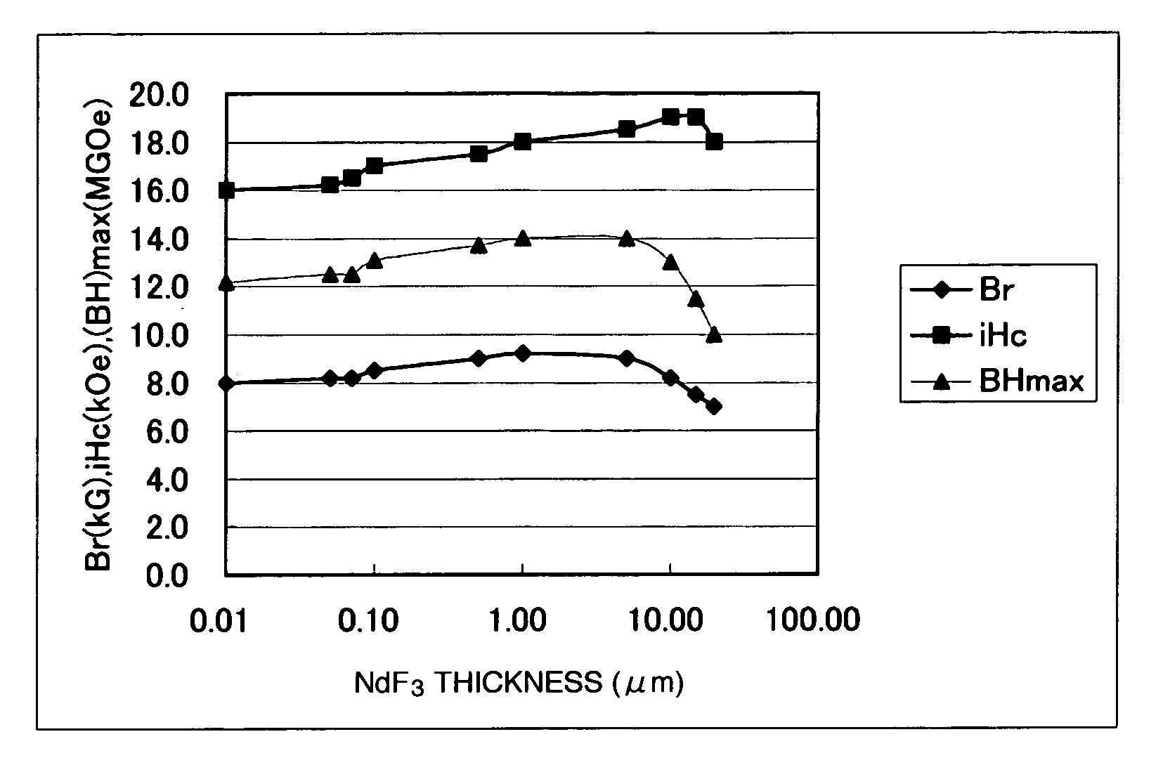
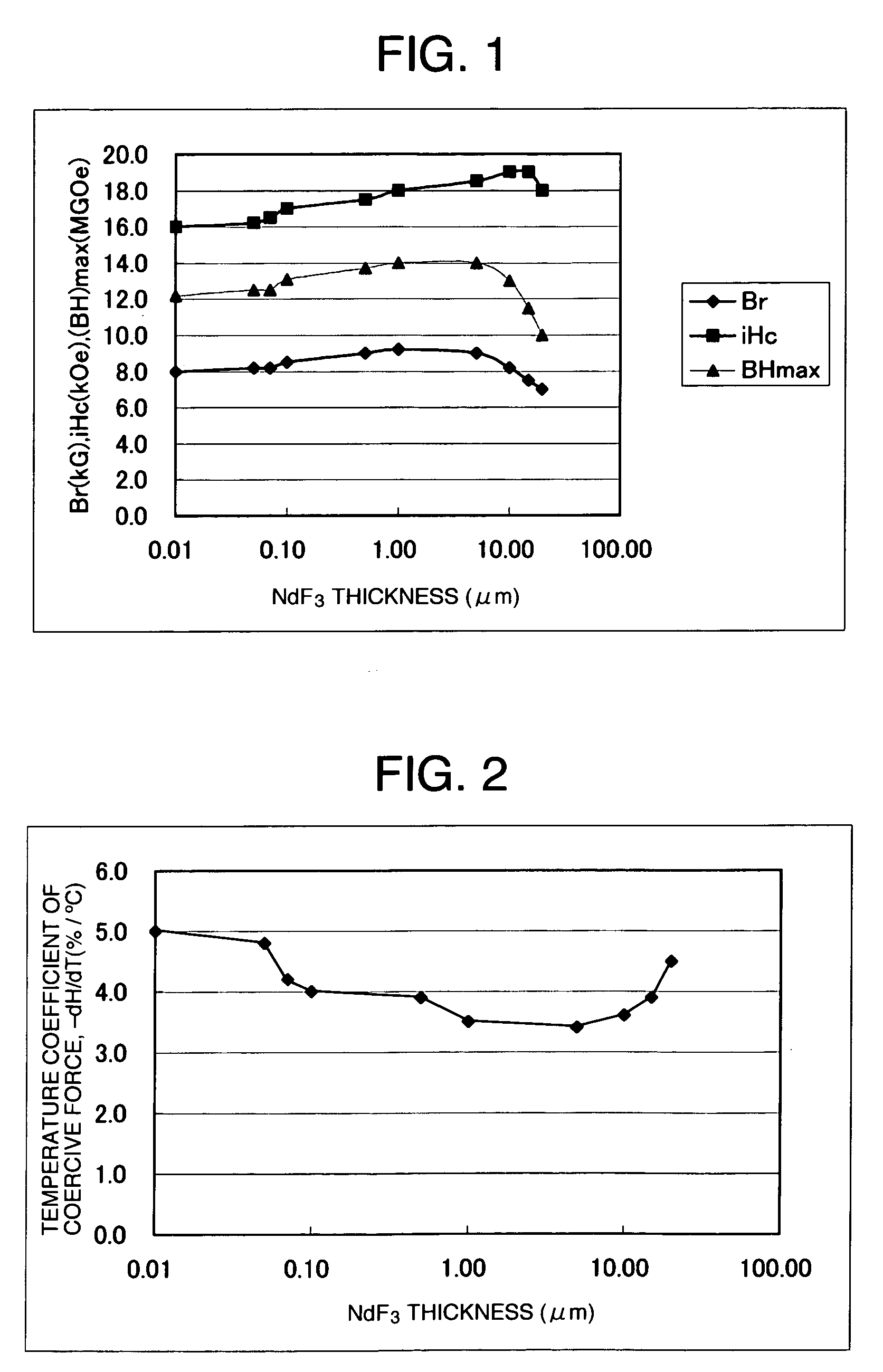
[0023]NdFeB alloy used was a powder having a particle size of about 100 μm subjected to a hydrogenation / dehydrogenation treatment, and the coercive force of this powder was 16 kOe. The fluoride compound to be mixed with the NdFeB powder was NdF3. NdF3 raw material powder was quenched using a quenching apparatus such as in FIG. 7 to form plate-like or ribbon-like powder. As shown in FIG. 7, raw material 102 was molten in an inert gas atmosphere 101 by arc melting using tungsten electrode 103, and by opening a shutter 107 of a nozzle hole 104, the molten NdF3 was atomized on a roll 105 from the nozzle hole 104. Ar gas was used as inert gas, and Cu or Fe based material was used for the roll 105, and the molten NdF3 was atomized on the roll 105 rotating at 500 to 5000 rpm by pressurizing it with Ar gas and utilizing the differential pressure. The resulting NdF3 powder was plate-like, and the NdF3 powder and NdFeB powder were mixed together such that NdF3 content became about 10 wt %. Th...
example 2
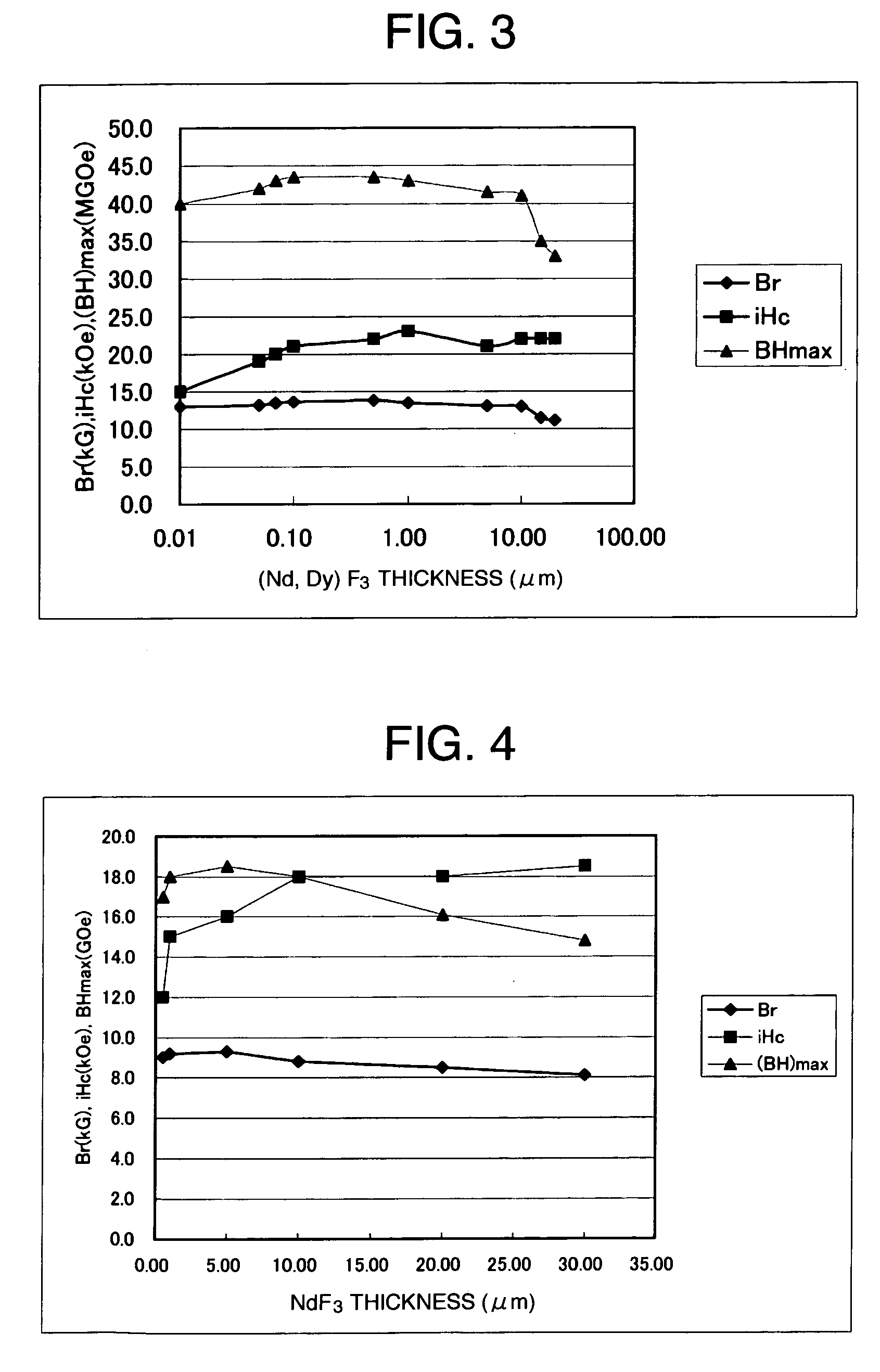
[0026]The NdFeB powder used in the example was intended for use of a bonded magnet or the like. The NdFeB powder used in the example 2 was powder of particle size of 5 μm diameter for use of sintering, in which main phase was Nd2Fe14B, and the grain boundary of the main phase was made of grown Nd rich phase. After being vacuumed to a degree of 1×10⁻⁵ Torr or less, (Nd, Dy)F3 powder was molten in an Ar atmosphere using arc melting, then the molten metal was pressurized and atomized on a surface of a single roll rotating in a vacuum atmosphere. The cooling rate of this processing was 104 to 106° C. / sec. The NdF3-5 wt % DyF3 powder (i.e. (Nd, Dy)F3 powder) formed by quenching, included powder having thickness of 10 μm or less and aspect ratio (the ration of vertical length and horizontal length) of 2 or more. By removing thick powder from such (Nd, Dy)F3 powder, NdF3 powder being as possible as thin was selected to be mixed with Nd—Fe—B alloy powder. The mixing amount of the (Nd, Dy)F3...
example 3
[0028]The NdFeB alloy was hydride dehydrated powder having a particle size of 150 μm, and the coercive force of the powder was 12 kOe. The fluoride compound added to the NdFeB powder was NdF3. The raw material powder of NdF3 was pulverized into powder having a mean particle diameter of 0.1 μm. It was mixed with the NdFeB powder such that the content of NdF3 became to 10%. The mixed powder was oriented and compressed using a magnetic field of 10 kOe, and thermally compression molded in a vacuum atmosphere (1×10⁻⁵ Torr) by energization. Under the molding condition of heating temperature at 700° C. and compression pressure of 3 t / cm2, an anisotropic magnet of 7 mm×7 mm×5 mm was made. The densities of the compacts made above were all 7.4 g / cm3 or more. Demagnetization curve of the molded anisotropic magnet was measured at 20° C. by applying a pulse magnetic field of 30 kOe or more in the anisotropic direction thereof.
[0029]The results are shown in FIG. 4. The NdF3 thickness is the avera...
PUM
| Property | Measurement | Unit |
|---|---|---|
| thickness | aaaaa | aaaaa |
| mean particle diameter | aaaaa | aaaaa |
| melting temperature | aaaaa | aaaaa |
Abstract
Description
Claims
Application Information
 - R&D
- Intellectual Property
- Life Sciences
- Materials
- Tech Scout
- Unparalleled Data Quality
- Higher Quality Content
- 60% Fewer Hallucinations
Browse by: Latest US Patents, China's latest patents, Technical Efficacy Thesaurus, Application Domain, Technology Topic, Popular Technical Reports.
© 2025 PatSnap. All rights reserved.Legal|Privacy policy|Modern Slavery Act Transparency Statement|Sitemap|About US| Contact US: help@patsnap.com


