Enhanced plasma etch process

a plasma etching and plasma technology, applied in the direction of fluid pressure measurement, instruments, chemistry apparatus and processes, etc., can solve the problems of non-uniformity, reworked or scrapped completely, and not always applicable in the production line fabrication of quantity and flow rate and throttle valve settings used in pilot programs, so as to reduce non-uniformity and increase the flow rate window of gas. , the effect of increasing the flow rate window

Inactive Publication Date: 2007-02-20
INTERSIL INC
View PDF10 Cites 7 Cited by
  • Summary
  • Abstract
  • Description
  • Claims
  • Application Information

AI Technical Summary

Benefits of technology

[0008]The method reduces the non-uniformity of etching in and / or increasing the flow rate window of the gas in the plasma etcher for a desired etch selectivity.

Problems solved by technology

Non-uniformity creates areas or dies within the wafer, which either must be re-worked or scrapped totally.
The quantity and flow rate and throttle valve settings used in the pilot programs are not always applicable in the production line fabrication.
When the turbo pump surges, the system cannot adequately control the low gas flows within the etching chamber and, therefore, leads to non-uniform etching.
The exhaust port at one side of the etching chamber makes the etching chamber very sensitive to rapid changes of flow and limits the ability to maintain uniformity across the etching chamber.
The method reduces the non-uniformity of etching in and / or increasing the flow rate window of the gas in the plasma etcher for a desired etch selectivity.

Method used


Image

  • Enhanced plasma etch process
  • Enhanced plasma etch process
  • Enhanced plasma etch process

Examples


Embodiment Construction

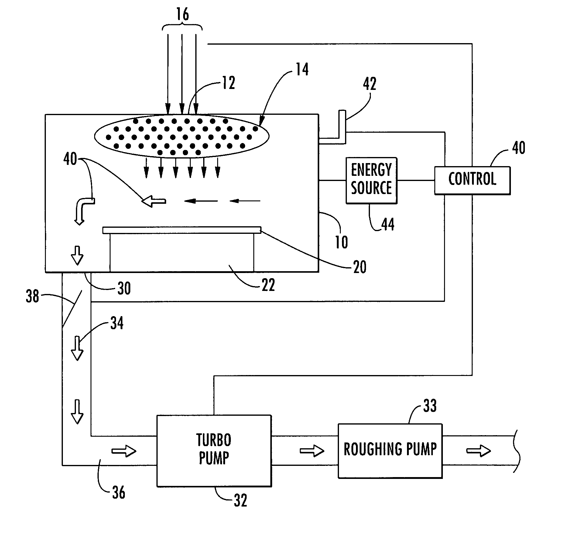
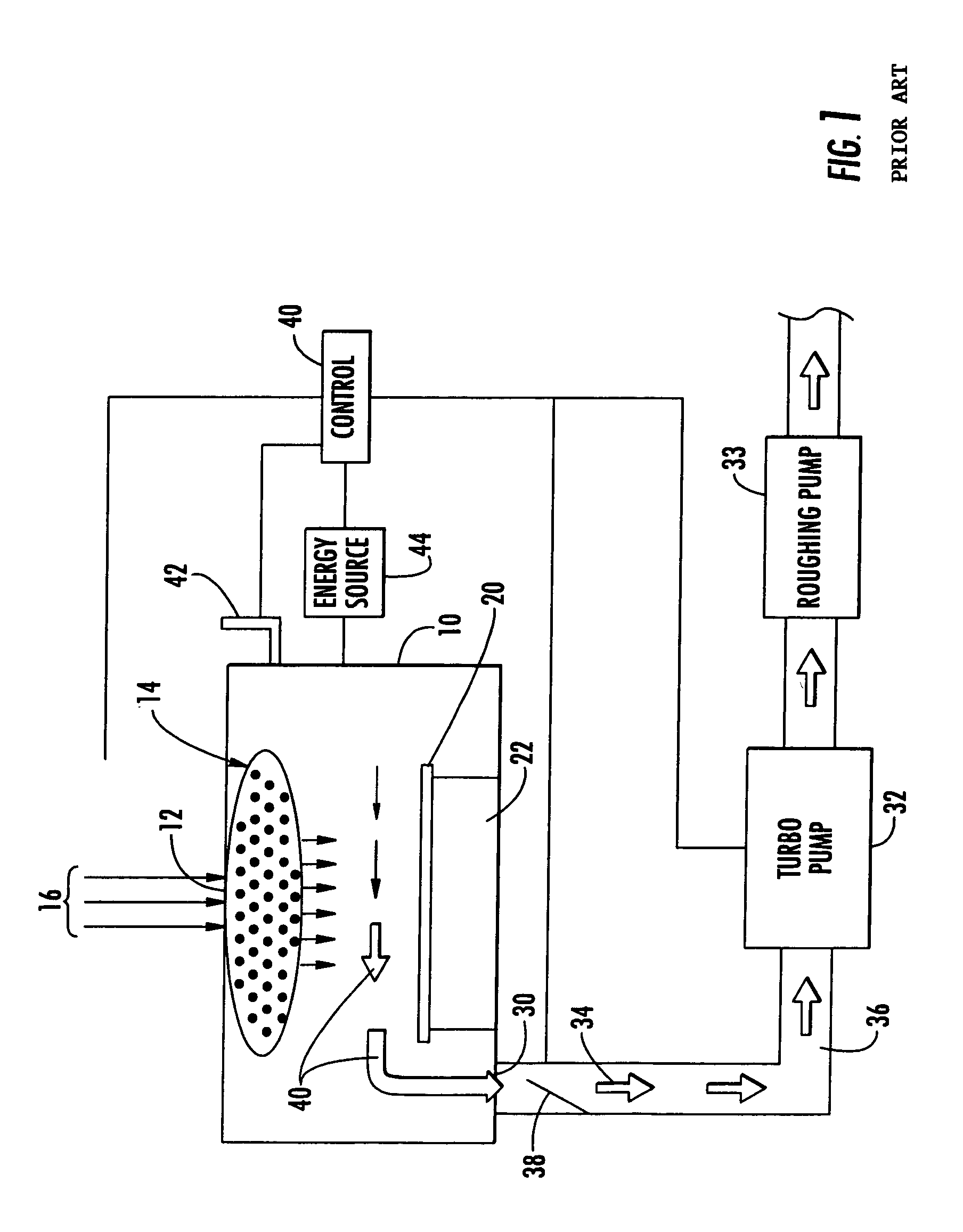
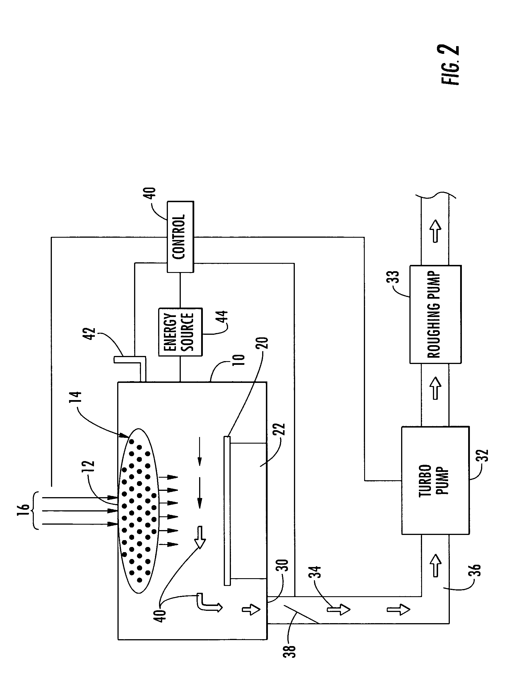
[0017]An etcher, as shown in FIG. 1, includes a plasma chamber 10 with an inlet 12 and a gas distributor plate 14 for one or more reactant gases 16, with or without the carrier gas. A wafer 20 with a plurality of dies or integrated circuit is shown resting on a pedestal 22 in the chamber 10. The object 20 to be etched may also be a micro electronic machine or flat panel display. An outlet or exhaust port 30 of the chamber 10 is connected to a turbo pump 32 and a roughing pump 33 by conduits 34 and 36 to remove by-products. A throttle valve 38 is provided in conduit 34. A control 40 is connected to a pressure transducer 42 to control the opening of the throttle valve 38 to maintain a constant pressure in the chamber 10 and an even exit flow. An rf energy source 44 is provided to create the plasma. The control system may also control the flow rate and proportion of the gases 16, the turbo and roughing pumps 32, 33 and the energy source 44. The control system is shown as a block and is...


PUM

PropertyMeasurementUnit
pressureaaaaaaaaaa
diameteraaaaaaaaaa
energyaaaaaaaaaa

Abstract

A method of operating a plasma etcher wherein gas is introduced into the etcher at a substantially higher rate than a previous standard rate for a desired etch selectivity, and the throttle valve's open value is set to a substantially greater open value than a previous standard open value for the desired etch selectivity. The method may also include introducing the gas at a lower pressure than the pressure of the previous standard pressure for a desired etch selectivity.

Description

CROSS-REFERENCE[0001]This application claims the benefit of U.S. Provisional Patent Application Ser. No. 60 / 564,983 filed on Apr. 26, 2004, which is incorporated herein by reference.BACKGROUND AND SUMMARY OF THE DISCLOSURE[0002]The present disclosure relates generally to plasma etch processes and, more specifically, to the plasma etch processes used in the manufacture of integrated circuits, MEMS (micro electronic machines), and flat panel displays.[0003]Integrated circuits include many layers (for example, oxides, nitrides, polycrystalline silicon, single metal films, sandwich stacked metal films, and other materials) that require plasma etching. Since integrated circuits are to be as planar as possible, there are etching processes that take place which require the ability to selectively etch one material compared to the other in order to produce planarization. Plasma etching includes introducing a reactant gas into the chamber and forming a plasma etching by applying an energy sou...

Claims


Application Information

Patent Timeline
Patent Type & Authority Patents(United States)
IPC IPC(8): G06F19/00C25F1/00H01L21/00H01L21/302H01L21/311
CPCH01L21/31116H01J37/32449
Inventor DECROSTA, DAVID A.
Owner INTERSIL INC
Why Eureka
Try Eureka