Frequency drift and phase error compensation in a VOFDM receiver

a phase error compensation and frequency drift technology, applied in the field of communication systems, can solve the problems of difficulty in extracting the information contained within symbols, source signals that provide data that are received by receivers within the communication system may sometimes undergo undesirable frequency drift, etc., and achieve the effect of increasing the probability

Inactive Publication Date: 2007-02-27
AVAGO TECH INT SALES PTE LTD
View PDF10 Cites 11 Cited by
  • Summary
  • Abstract
  • Description
  • Claims
  • Application Information

AI Technical Summary

Benefits of technology

[0017]The present invention is implemented within a wireless modem receiver in one embodiment; this communication system employs the VOFDM portion of the Broadband Wireless Internet Forum (BWIF) standard set. It is also noted that the present invention would benefit any multi-...

Problems solved by technology

These symbols may undergo some undesirable corruption due to the imperfection of the communication channel.
However, there is typically some difficulty in extracting the information contained within these symbols after they have been undesirably altered within the communication channel.
However, even after the incoming signal has been equalized, the extraction of the data, that has undergone some alteration due to the channel effects, is still a probabilistic determination.
To further complicate the issue, the source signal that provides the data that are received by a receiver within the communication system may sometimes undergo undesirable frequency drift.
The effect can be phase error and/or frequency drift in the received data, thereby making the extraction of the data even that much more difficult at the receiver end.
However, frequency drift and phase error may actually exist within...

Method used


Image

  • Frequency drift and phase error compensation in a VOFDM receiver
  • Frequency drift and phase error compensation in a VOFDM receiver
  • Frequency drift and phase error compensation in a VOFDM receiver

Examples


Embodiment Construction

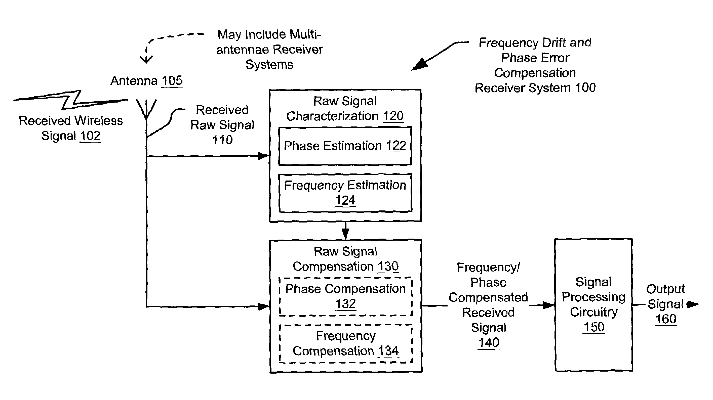
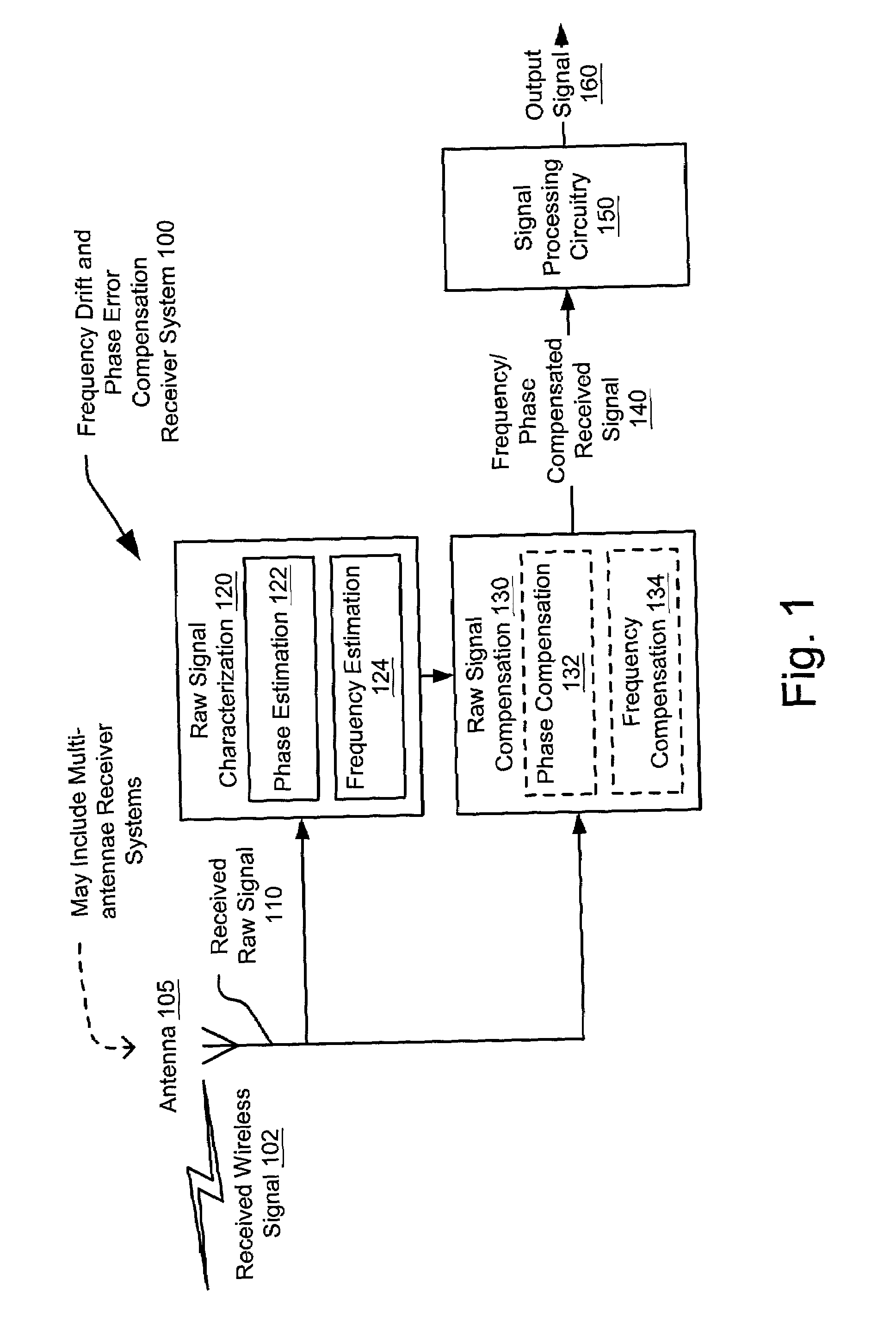
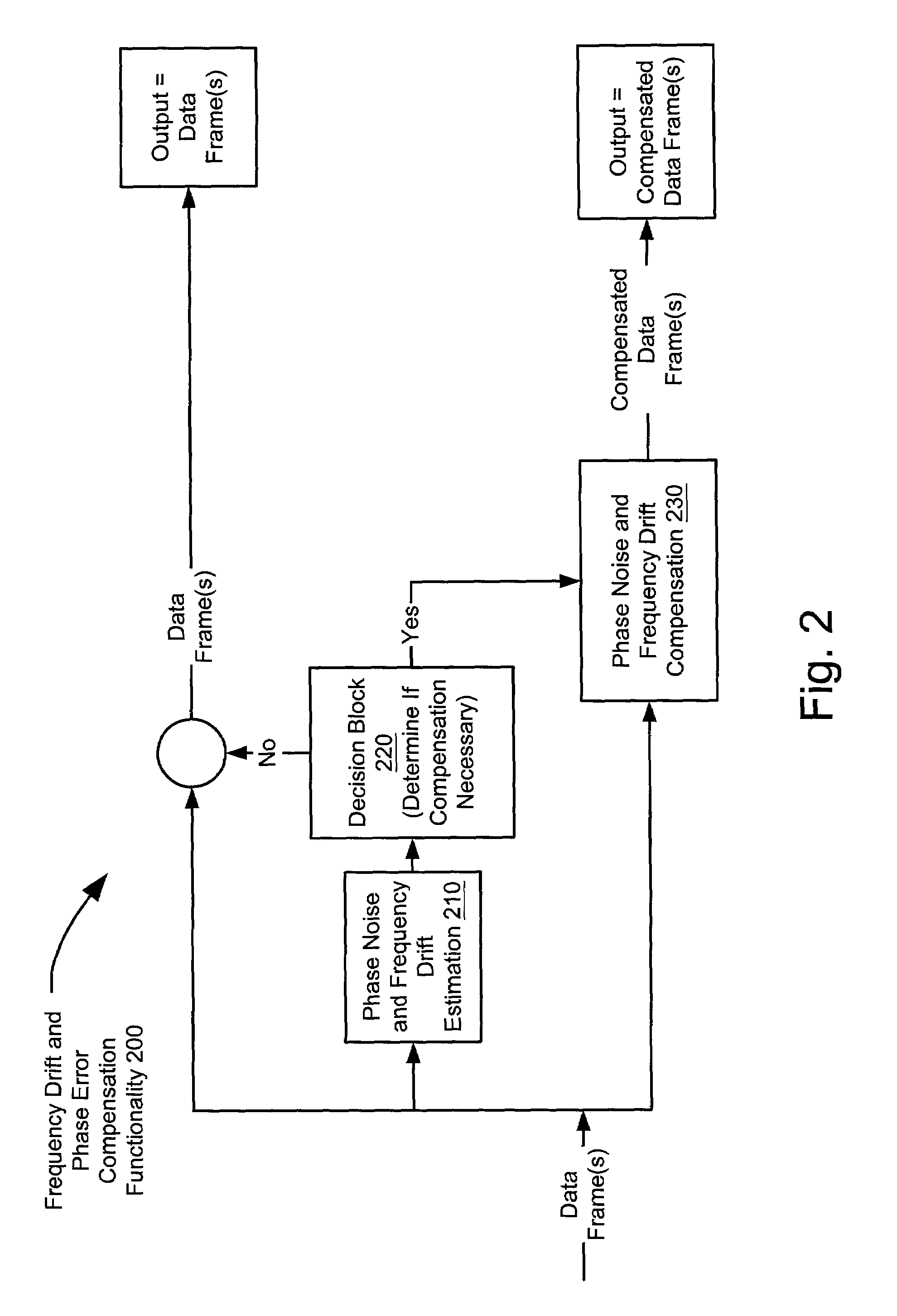
[0033]The present invention is operable to determine whether there is any phase error and / or frequency shift in an incoming signal, and to compensate for any of those errors before providing the received signal to subsequent signal processing circuitry for symbol processing. There are a variety of means by which the phase error and frequency drift estimation and compensation may be performed without departing from the scope and spirit of the invention, and any method may be employed to determine the existence of these effects before compensating for them when deemed necessary. The present invention is operable within a receiver circuitry; the receiver circuitry includes a wireless modem in certain embodiments.

[0034]The present invention is operable within the VOFDM portion of the BWIF standard set. The VOFDM standard defines the physical layer and additional layers in which a plurality, e.g., up to 1,024 separate carriers (tones) carry data (data tones), null information (zero ton...


PUM


Abstract

Improved frequency drift and phase error compensation in a VOFDM receiver. The invention is operable to compensate for frequency drift and phase error within a window that may include a single frame, a sub-frame, or multiple frames. The compensation is performed after having performed estimation of the phase within the particular window; any phase error and frequency drift may be identified and an appropriate form of compensation may be identified to perform curve fitting of the phase within the compensation window. The curve fitting of the phase is performed using linear techniques in one embodiment; an average phase and appropriate slope/ramp are calculated to match the phase as accurately as possible. Other alternative compensation techniques may also be performed, including higher order curve matching techniques. The receiver is operable to perform any necessary compensation before passing the now-compensated data to a symbol processing functional block.

Description

CROSS REFERENCE TO RELATED APPLICATIONS[0001]The following U.S. Utility Patent Applications are hereby incorporated herein by reference in their entirety and made part of the present U.S. patent application for all purposes:[0002]1. U.S. Utility patent application Ser. No. 10 / 109,978, entitled “OPTIMAL DECISION METRIC APPROXIMATION IN BIT-SOFT DECISIONS,” filed Saturday, Mar. 30, 2002, pending.[0003]2. U.S. Utility patent application Ser. No. 10 / 112,009, entitled “MODIFIED BRANCH METRICS FOR PROCESSING SOFT DECISIONS TO ACCOUNT FOR PHASE NOISE IMPACT ON CLUSTER VARIANCE,” filed Saturday, Mar. 30, 2002, pending.[0004]3. U.S. Utility patent application Ser. No. 10 / 112,567, entitled “CHARACTERIZING CHANNEL RESPONSE IN A SINGLE UPSTREAM BURST USING REDUNDANT INFORMATION FROM TRAINING TONES.” filed Saturday, Mar. 30, 2002, pending.[0005]4. U.S. Utility patent application Ser. No. 10 / 114,023, entitled “VOFDM RECEIVER CORRELATION MATRIX PROCESSING USING FACTORIZATION,” filed Mar. 30, 2002,...

Claims


Application Information

Patent Timeline
IPC IPC(8): H04L7/00H04L27/00H04L27/26
CPCH04L27/0014H04L27/2657H04L27/2676H04L2027/0067
Inventor KOLZE, THOMAS J.
Owner AVAGO TECH INT SALES PTE LTD
Why Eureka
Try Eureka