Fiber optic impact detection system

a sensor system and fiber optic technology, applied in the direction of optical radiation measurement, force/torque/work measurement apparatus, instruments, etc., can solve the problems of the inability to use a system, and the inability to detect the location of a mod, etc., to achieve the effect of easy adaptation to existing structures, low weight and cost effectiveness

Inactive Publication Date: 2007-03-13
FIBER OPTIC SYST TECH
View PDF10 Cites 46 Cited by
  • Summary
  • Abstract
  • Description
  • Claims
  • Application Information

AI Technical Summary

Benefits of technology

[0012]A further object of the invention is to provide a light weight, cost effective damage sensor and system that employs standard optical fibers and is suitable for weight critical applications.
[0013]A further object of the invention is to provide a sensor that is easily adapted to existing structures.

Problems solved by technology

The probability of impacts by high energy micrometeoroids or orbital debris (MOD) that might breach the protection system is sufficiently high that loss of a module, the vehicle, or human life is possible.
Unfortunately, there is no adequate system currently available that will permit the detection of the location of an MOD impact, the direction from which the impact occurred, the size of the impacting object and the extent of the damage caused by the impact.
That system is unsuitable for many applications because the failure strength of the fibers must be tailored for each case to ensure that the fiber will break at some acceptable damage threshold for the structure.
In addition, such a system is not amenable to non-composite structures or in a retrofit application as the fibers must be embedded in the composite material.
; however, in that system, untreated optical fibers are looped repeatedly in two separate X-direction and Y-direction grids before being embedded in or bonded onto a composite structure.
However, the attempt to increase efficiency and reduce complexity by covering a larger area with a single fiber laid in the looping pattern is defeated once a fiber is broken by an impact, because a large portion of the surface is then left unmonitored.
The coupling of a multiplicity of fibers into the laser diode is required to accommodate large structures and intensity loss may make that impractical.
Furthermore, without a closely spaced grid of fibers, localizing and quantifying the damaged area may not be possible with that system.
While that system has the potential to track the changes in a material following impact, configuring the multitude of sensors required for a large structure would be bulky and costly as a light splitter and optical phase angle detector are required for each sensor.

Method used


Image

  • Fiber optic impact detection system
  • Fiber optic impact detection system
  • Fiber optic impact detection system

Examples


Embodiment Construction

[0033]A preferred embodiment and its use will be set forth in detail with reference to the drawings, in which like reference numerals refer to like elements throughout.

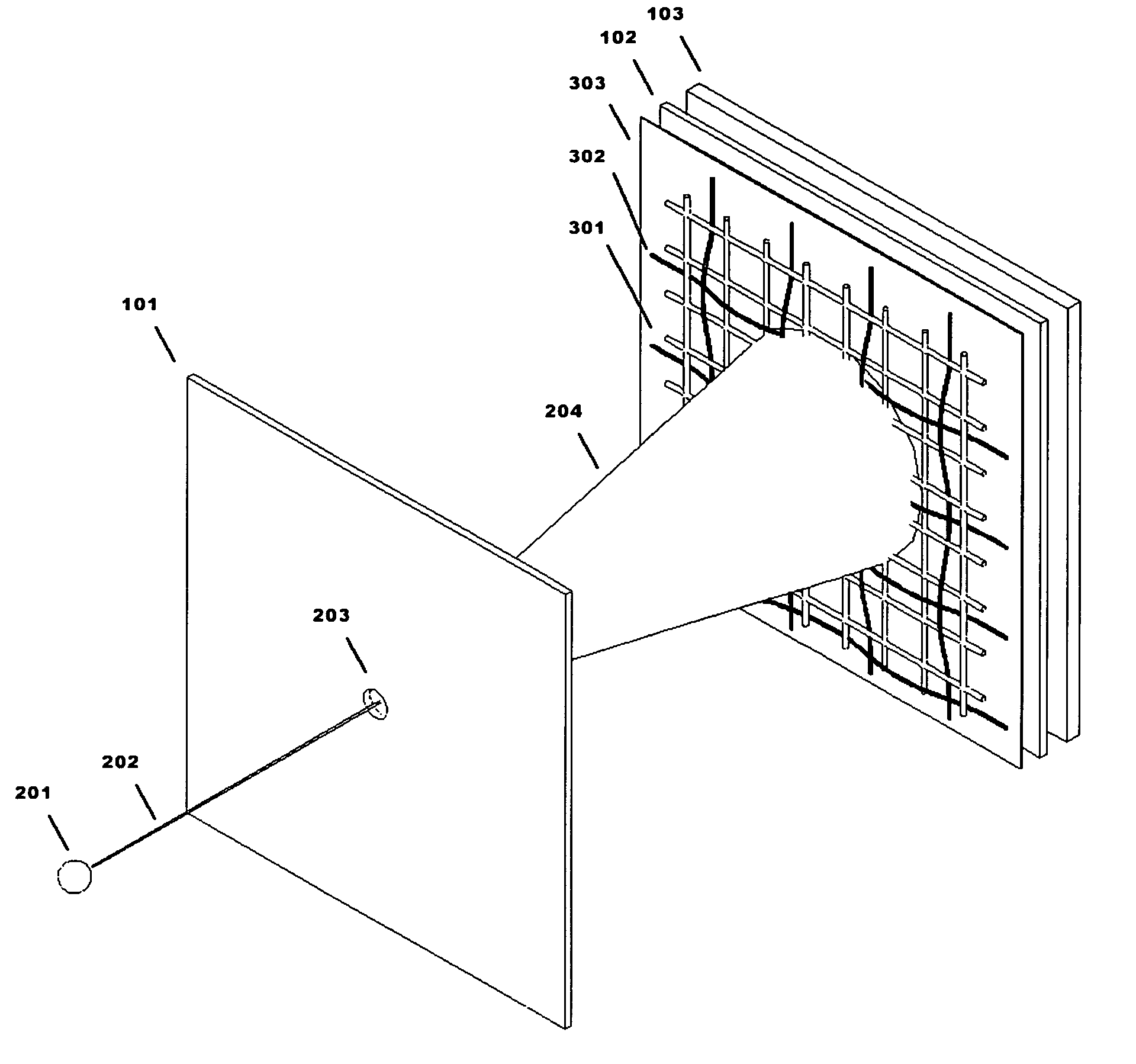
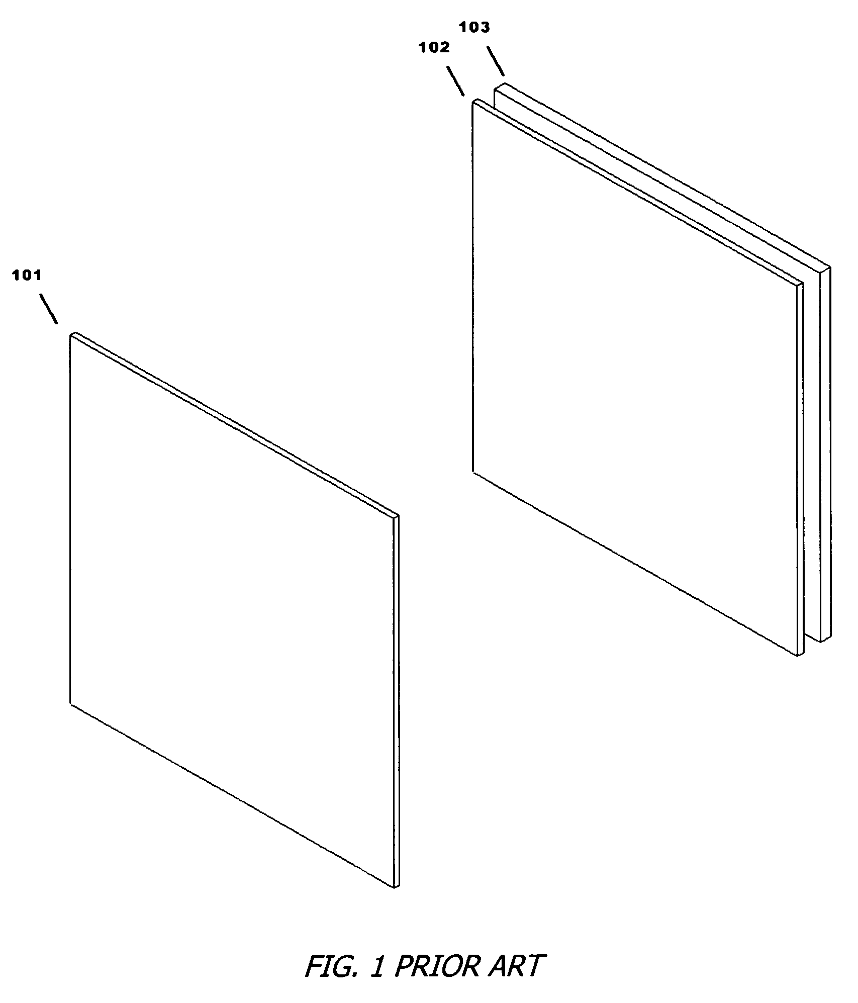
[0034]Referring to FIG. 1, a section of the typical structure used in spacecraft and other vehicle construction is shown. The structure is comprised of a first surface that acts as a bumper shield 101, an energy absorbing layer 102 made of multiple plies of a material such as those sold under the trade names Nextel® or Kevlar®, and a second surface 103 that acts as the structural and pressure vessel wall.

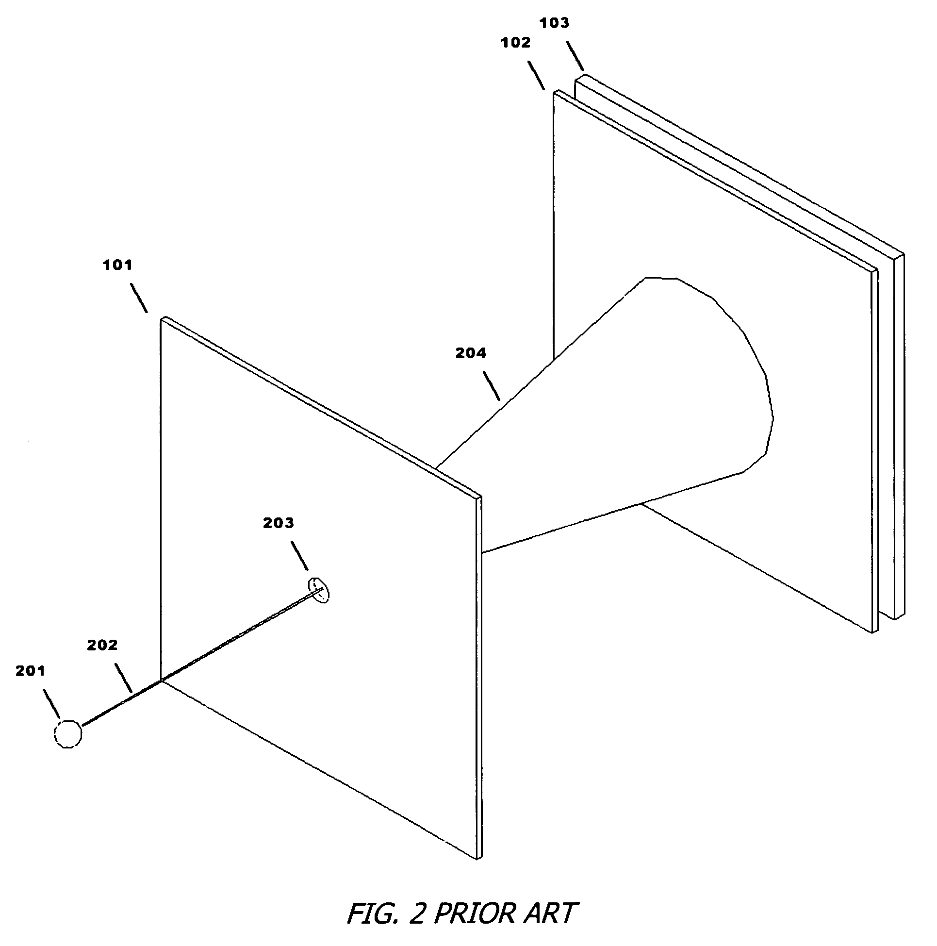
[0035]Referring to FIG. 2, when a high energy object or MOD particle 201 travels along a trajectory 202 and strikes the bumper shield 101, it creates an entry hole 203 with a diameter that is proportional to the diameter of the MOD particle 201. The primary cause for concern is not the entry hole 203, but the damage to the second surface 103 that is caused by the debris plume 204 as it strikes the energy absorbing lay...


PUM


Abstract

Closely spaced conventional optical fibers are arranged in a grid placed between a first surface and a second surface. A penetrating impact onto the first surface results in a hole of a size proportional to the diameter and velocity of the impacting object. The size and shape of the debris plume that travels between the first and second surfaces is also proportional to the diameter and velocity of the impacting object. If the debris plume is sufficiently energetic, a number of the fibers in the grid are broken. The size and shape of the area defined by the broken fibers can be determined simply by determining which fibers are no longer transmitting light. Analytical methods are then used to relate the extent of the damaged area to the location of an MOD impact, the direction from which the impact occurred, and the size of the impacting object.

Description

REFERENCE TO RELATED APPLICATION[0001]The present application claims the benefit of U.S. Provisional Patent Application No. 60 / 553,959, filed Mar. 18, 2004, whose disclosure is hereby incorporated by reference in its entirety into the present disclosure.FIELD OF THE INVENTION[0002]The invention is directed to an improved fiber optic based sensor system to detect and quantify the area of damage caused by an impacting object and more particularly the area of damage caused by the impact of a hypervelocity object. The invention is further directed to a method for using such a sensor system.DESCRIPTION OF RELATED ART[0003]The use of bumper shields and energy absorbing materials to minimize the damage caused by impacts is well known, particularly for aircraft, automotive or spacecraft applications. Such systems are used to enhance safety and to reduce the weight requirements for the protection of manned structures.[0004]Most space vehicles, including the current space station, are compris...

Claims


Application Information

Patent Timeline
Patent Type & Authority Patents(United States)
IPC IPC(8): H01J5/16
CPCG01L5/0052G01M5/0033G01M5/0091G01V8/24G01M11/085G01M11/086G01M7/08
Inventor MORISON, W. DONALDTENNYSON, RODERICK C.CHERPILLOD, THIERRY
Owner FIBER OPTIC SYST TECH
Why Eureka
Try Eureka