
Method, apparatus, and computer program product for implementing dynamic cosimulation

a dynamic cosimulation and computer program technology, applied in the field of data processing, can solve the problems of large wait time, ineffective use of hardware accelerators, incorrect behavior, etc., and achieve the effect of not having a negative

Inactive Publication Date: 2007-03-13
IBM CORP
View PDF15 Cites 13 Cited by
  • Summary
  • Abstract
  • Description
  • Claims
  • Application Information

AI Technical Summary

Benefits of technology

The present invention provides a method, apparatus, and computer program product for implementing dynamic cosimulation. This technology allows for the dynamic disengagement and re-engagement of a primary simulator and secondary simulator for data exchange. The invention also includes various user-defined optimization control signals for disabling the cosimulation bridge and re-engaging the simulators. The technical effects of this invention include improved efficiency, flexibility, and responsiveness in conducting simulation experiments.

Problems solved by technology

This results in large wait times and causes ineffective use of hardware accelerators.
If too large of an interval is specified signal transitions may be missed and this can result in incorrect behavior.
A problem with parallel cosimulation is that the overhead of the information exchange between simulators in such an environment can become significant when one of the simulation engines is a hardware accelerator or when the exchange is being done over a network.
Known cosimulation tools used to optimize the inter-process cosimulation between simulators in the software bridge between the simulators may be very efficient for their intended tasks; however such solutions are very specific for the type of interface being modeled, and therefore do not provide a generic method of optimization.
Since the optimization is implemented in software such solutions become inefficient for use in hardware accelerators.

Method used


Image

  • Method, apparatus, and computer program product for implementing dynamic cosimulation
  • Method, apparatus, and computer program product for implementing dynamic cosimulation
  • Method, apparatus, and computer program product for implementing dynamic cosimulation

Examples


Embodiment Construction

[0021]In accordance with features of the preferred embodiment, a simple method is provided that allows the optimization of the inter-process communication to be implemented in logic connected to the cosimulation bridge interfaces. This provides the user with total control and flexibility with regard to the optimization of inter-process communication between the simulators, and the ability to write the optimization logic in synthesizable RTL. Fully synthesizable RTL executes at full hardware acceleration speeds in a hardware accelerator, and thus minimizes the amount of software interaction required with the hardware accelerator.

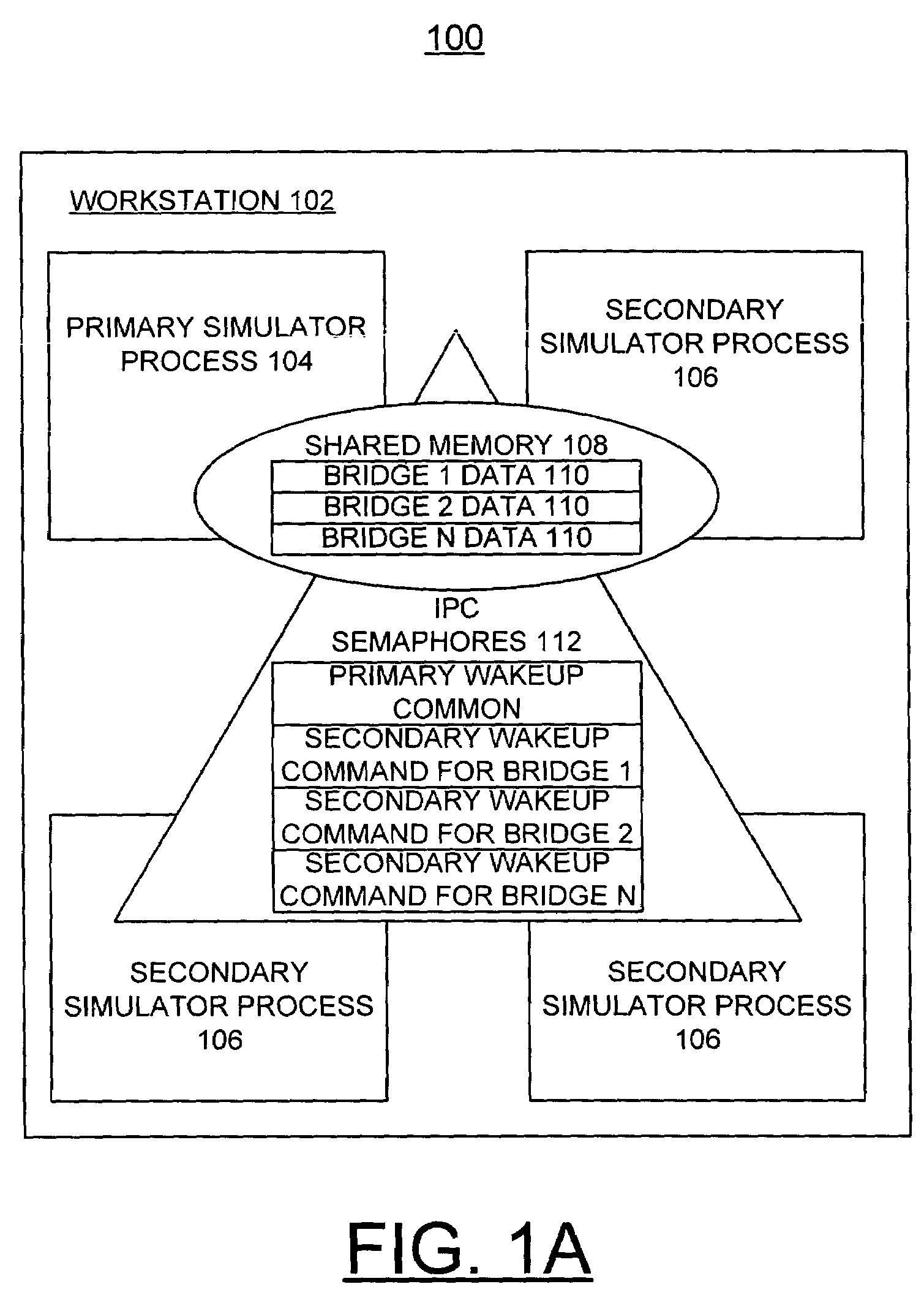
[0022]Having reference now to the drawings where like reference numerals designate corresponding parts in the various figures, in FIG. 1A there is shown a single workstation cosimulation bridge system generally designated by reference character 100 for implementing dynamic cosimulation methods in accordance with the preferred embodiment. The single workstatio...


PUM


Abstract

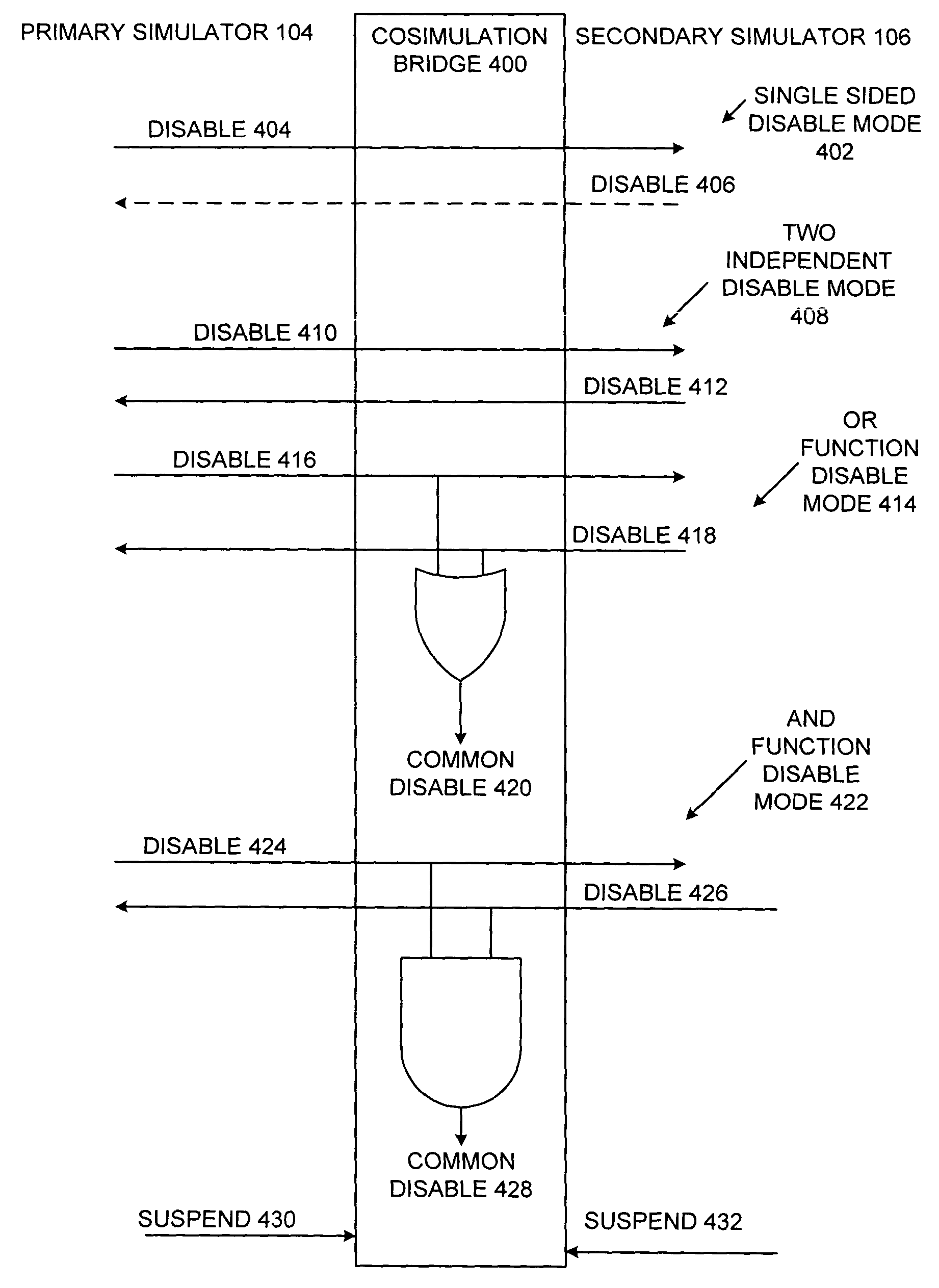
Dynamic cosimulation is implemented using a cosimulation bridge for data exchange between a primary simulator and a secondary simulator, and a plurality of user selected optimization control signals defined over the cosimulation bridge. At least one user selected optimization control signal is identified for disabling the cosimulation bridge. The primary simulator and secondary simulator are dynamically disengaged for ending data exchange responsive to disabling the cosimulation bridge. Responsive to optimization control signal going inactive, the primary simulator and secondary simulator are dynamically re-engaged for data exchange. The optimization control signals include a single sided disable; a two independent disable; a functional OR disable; a functional AND disable, and suspend signals. The single sided disable and the two independent disable enable disabling one side of the cosimulation bridge and not the other side. Both sides of the cosimulation bridge are disabled together using the functional OR disable and the functional AND disable.

Description

FIELD OF THE INVENTION[0001]The present invention relates generally to the data processing field, and more particularly, relates to a method, apparatus and computer program product for implementing dynamic cosimulation.DESCRIPTION OF THE RELATED ART[0002]Computer simulation of digital hardware systems has become a common technique used for the verification of hardware systems, reducing cost and time required. Sometimes it is necessary to create a software bridge between hardware description language (HDL) simulators for verification of an application specific integrated circuit (ASIC) or a custom Integrated Circuit (IC). The bridging between two software simulators is called cosimulation. These software simulators can be bridged via a software linkage joining the two simulators to form a single process, a fast inter-process communication on the same workstation, and a Transmission Control Protocol / Internet Protocol (TCP / IP) socket based communication over a network.[0003]Conventiona...

Claims


Application Information

Patent Timeline
Patent Type & Authority Patents(United States)
IPC IPC(8): G06F17/50G06F9/45
CPCG06F17/5022G06F2217/86G06F30/33G06F2117/08
Inventor SCHUPPE, RAYMOND WALTER MANFRED
Owner IBM CORP
Learn More