
Configurable interconnection of multiple different type functional units array including delay type for different instruction processing

a functional unit array and interconnection technology, applied in the direction of generating/distributing signals, instruments, pulse techniques, etc., can solve the problems of reducing the efficiency of the second direction, reducing the overall shape of the data processing block, and unable to achieve the most efficient arrangement in the second direction, so as to increase the range of processing that can be handled by a configuration of operation units, the effect of increasing the range of processing

Inactive Publication Date: 2007-03-13
FUJIFILM BUSINESS INNOVATION CORP
View PDF23 Cites 4 Cited by
  • Summary
  • Abstract
  • Description
  • Claims
  • Application Information

AI Technical Summary

Benefits of technology

The present invention is an integrated circuit device that includes a matrix of operation units arranged in first and second directions. The operation units have different data paths suited for special-purpose processing. The device also includes first and second wire sets that transfer input and output data between the operation units. The arrangement of the wire sets allows for efficient use of space and high processing speed. The technical effects of the invention include improved area efficiency, increased integration, and favorable AC characteristics.

Problems solved by technology

When the number of one type of operation unit, for example, a first type of operation unit, is much higher than the number of a second type of operation unit, if the first type of operation units are positioned simply in accordance with the length of the arrangements of the second type of operation units, the overall shape of the data processing block ends up being too long and thin, which may reduce the area efficiency.
When the sizes of the various types of operation units in the first direction are different, the most efficient arrangement in the second direction cannot be achieved.

Method used


Image

  • Configurable interconnection of multiple different type functional units array including delay type for different instruction processing
  • Configurable interconnection of multiple different type functional units array including delay type for different instruction processing
  • Configurable interconnection of multiple different type functional units array including delay type for different instruction processing

Examples


Embodiment Construction

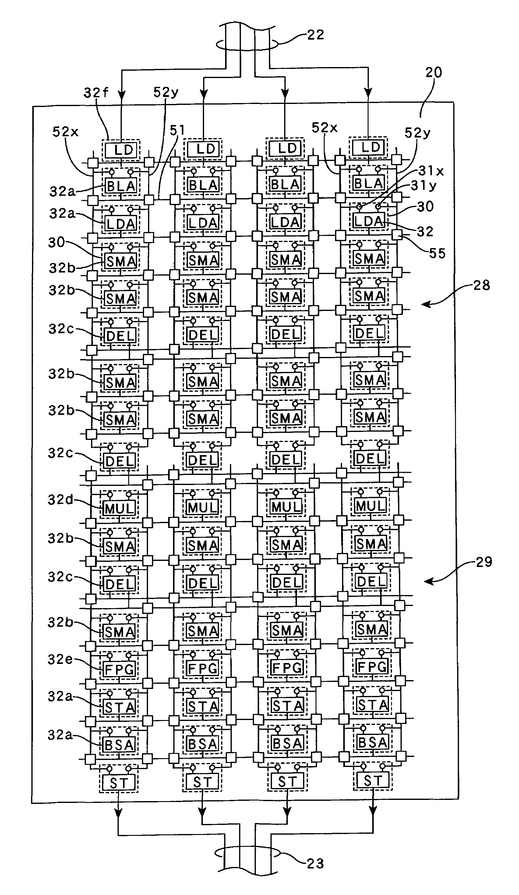
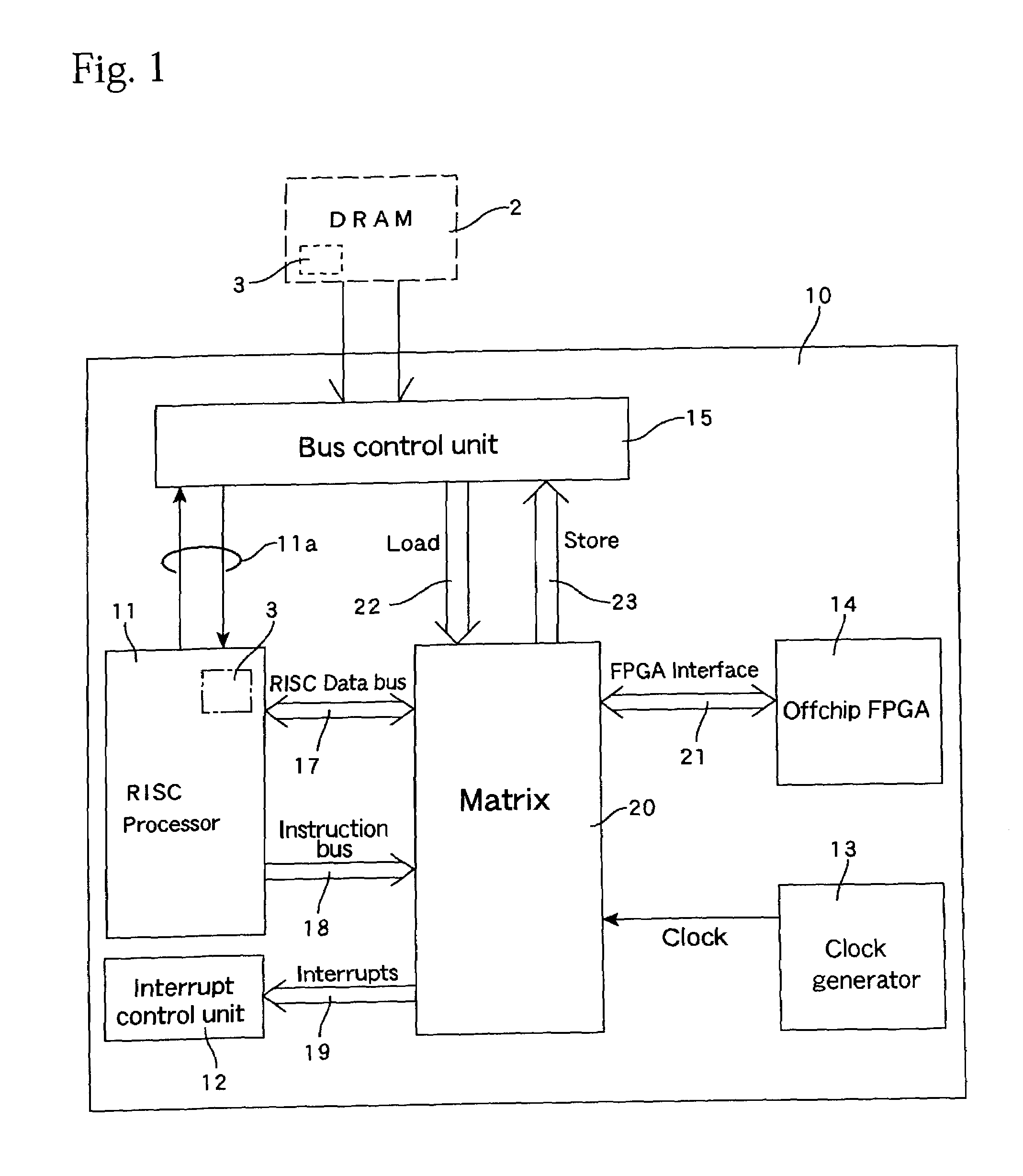
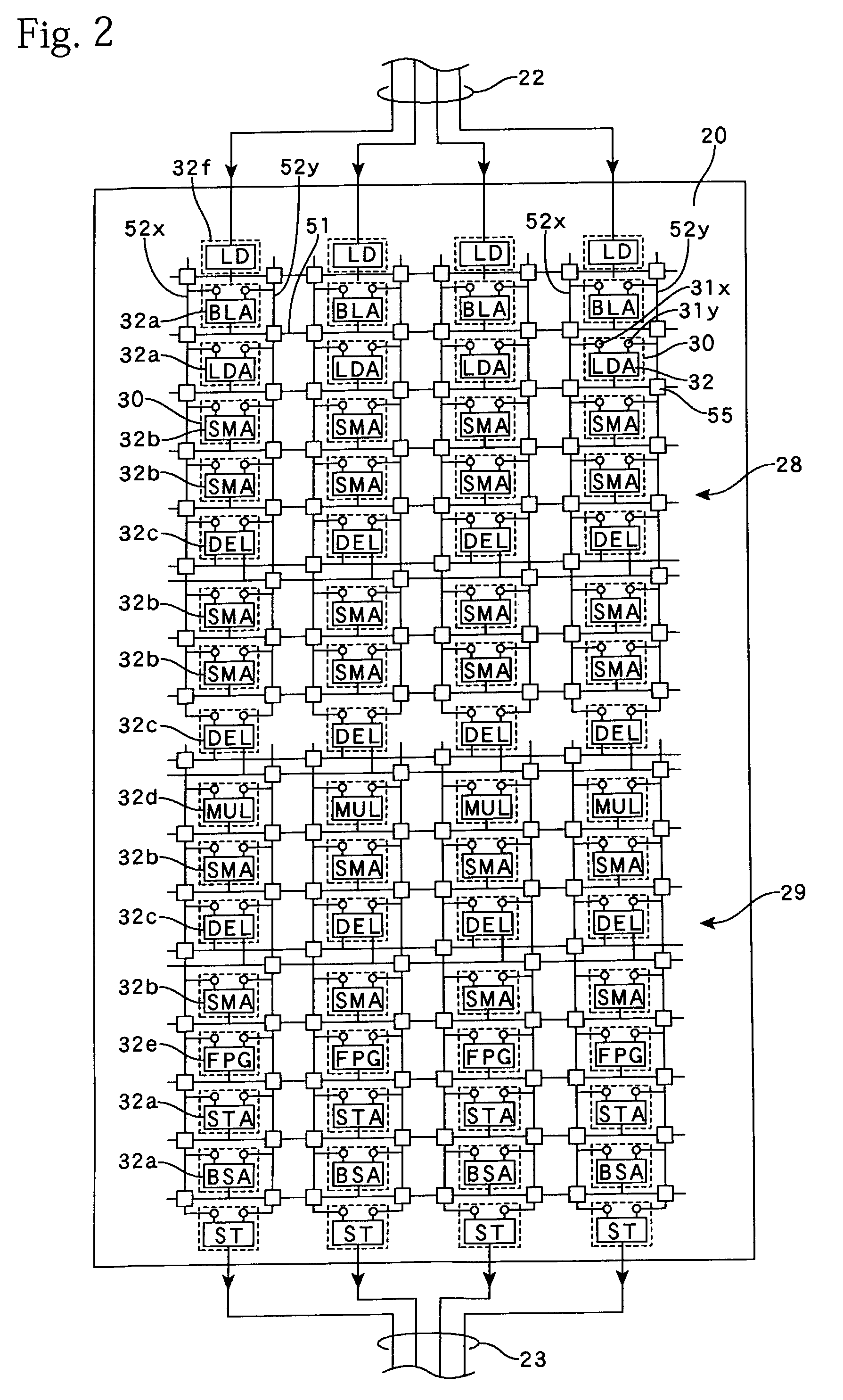
[0052]The following describes the present invention with reference to the attached drawings. FIG. 1 shows an example where a system LSI 10 is configured as an integrated circuit device according to the present invention. This system LSI 10 includes a general-purpose processor 11, such as a RISC processor for performing general-purpose processing, includes error handling, based on instructions in an execution program 3, and a data processing block (hereafter referred to as the “matrix unit” or “matrix”) 20 where a data flow or a pseudo data flow that is suited to special-purpose data processing is formed by a plurality of operation units that are arranged in a matrix. The general-purpose processor (hereafter also referred to as the “RISC”) 11 also controls the configuration of the matrix 20 based on the execution program 3, so that the configuration of the matrix 20 can be dynamically changed. The system LSI 10 also includes an interrupt control unit 12 for controlling the handling o...


PUM


Abstract

An integrated circuit device with a data processing block is provided, the data processing block including a plurality of operation units that are arranged in a matrix, a plurality of first wire sets that extend in a first direction in the matrix and transfer input data of each operation unit, a plurality of second wire sets that extend in a second direction in the matrix and transfer output data of each operation unit, and a plurality of switching units that are arranged at each intersection between the first and second wire sets and can select and connect any wire in the first wire sets and any wire in the second wire sets. The plurality of operation units include a plurality of types of operation units with different data paths that are suited to special-purpose, processing, with an arrangement of operation units of the same type in the first direction or the second direction being formed in at least part of the data processing block. The functioning of the integrated circuit device can be dynamically changed by changing the configuration of the operation units and the integrated circuit device is composed of operation units with different data paths that are suited to special-purpose processing so that the integrated circuit device is both compact and economical.

Description

[0001]This is the U.S. national phase of International Application No. PCT / JP02 / 05047 filed May 24, 2002, the entire disclosure of which is incorporated herein by reference.TECHNICAL FIELD[0002]The present invention relates to an integrated circuit device in which a plurality of operation units are arranged in a matrix.RELATED ART[0003]FPGA (Field Programmable Gate Arrays) are conventionally known as integrated circuit devices in which logic gates are laid out in arrays and the interconnects between the logic gates can be freely changed. The construction of an FPGA can be roughly classified into a plurality of logic blocks and wiring that connects these logic blocks. A logic block is a circuit unit that includes a lookup table and a flip-flop, and, by changing the set values in the lookup table, functions as a logic gate for achieving a logic function, such as an AND or an OR, in bit units. A plurality of logic blocks are arranged in an array or in a matrix and are connected by row ...

Claims


Application Information

Patent Timeline
Patent Type & Authority Patents(United States)
IPC IPC(8): G06F15/76G06F15/78G06F17/50
CPCG06F17/5045G06F15/7867G06F30/30H03K19/173
Inventor IKEDA, KENJISHIMURA, HIROSHISATO, TOMOYOSHI
Owner FUJIFILM BUSINESS INNOVATION CORP
Learn More