Electrode for rechargeable lithium battery and rechargeable lithium battery

a rechargeable lithium battery and lithium battery technology, applied in the direction of secondary cell servicing/maintenance, cell component details, cell components, etc., can solve the problems of reducing the energy density, increasing the volume of the electrode, and forming wrinkles, so as to improve the charge-discharge cycle characteristics

Inactive Publication Date: 2007-03-20
SANYO ELECTRIC CO LTD
View PDF67 Cites 194 Cited by
  • Summary
  • Abstract
  • Description
  • Claims
  • Application Information

AI Technical Summary

Benefits of technology

[0005]The inventors of this application have found that an electrode including a thin film composed of active material, e.g., a microcrystalline or amorphous silicon thin film, deposited on a current collector by a film-forming process such as a sputtering or CVD process exhibits improved charge-discharge cycle characteristics and is suitable for incorporation in rechargeable lithium batteries, as demonstrated in Reference Experiments 1–8 which will be later described.

Problems solved by technology

However, since the thin film of active material expands and shrinks as it stores and releases lithium, a stress is engendered in the current collector during a charge-discharge reaction and occasionally causes formation of wrinkles in such an electrode for a rechargeable lithium battery.
The formation of wrinkles not only increases a volume of the electrode but also disturbs uniformity of an electrode reaction, resulting in the reduction of an energy density.

Method used


Image

  • Electrode for rechargeable lithium battery and rechargeable lithium battery
  • Electrode for rechargeable lithium battery and rechargeable lithium battery
  • Electrode for rechargeable lithium battery and rechargeable lithium battery

Examples


reference experiment 1

[0111](Fabrication of Negative Electrode)

[0112]A microcrystalline silicon thin film was formed on a rolled copper foil (18 μm thick) by a CVD method, using the rolled copper foil as a substrate, silane (SiH4) as a source gas and a hydrogen gas as a carrier gas. Specifically, the copper foil as a substrate was placed on a heater within a reaction chamber. An interior of the reaction chamber was evacuated by a vacuum evacuator to a pressure of 1 Pa or lower. The silane gas as a source gas and the hydrogen (H2) gas as a carrier gas were introduced via a source gas inlet port. The substrate was heated to 180° C. on the heater. A degree of vacuum was adjusted by the vacuum pumping apparatus to a reaction pressure. An RF power supply was operated to excite a radio frequency wave which is introduced via an electrode to induce a glow discharge. Detailed thin-film forming conditions are listed in Table 1. In Table 1, a volumetric unit, sccm, indicates a volumetric flow rate (cm3 / minute) of a...

reference experiment 2

[0132]The procedure used in Reference Experiment 1 to construct the battery A1 was followed, except that an electrolytic copper foil (18 μm thick) was used for the current collector as a substrate. That is, a microcrystalline silicon thin film (about 10 μm thick) was deposited on the electrolytic copper foil to fabricate an electrode a3. Using this electrode, a battery A3 was constructed.

[0133]Also, the rolled copper foil used in Reference Experiment 1 was subjected to a one-minute griding treatment with a #400 or #120 emery paper to provide a ground copper foil. The procedure used in Reference Experiment 1 to construct the battery A1 was followed, except that such a ground copper foil was used for the current collector as a substrate. That is, a microcrystalline silicon thin film (about 10 μm thick) was deposited on the copper foil to fabricate an electrode. The electrode fabricated using the copper foil ground with a #400 emery paper was designated as an electrode a4 and the elect...

reference experiment 3

[0138]The batteries A1 and A3 respectively constructed in Reference Experiments 1 and 2 were further subjected to a charge-discharge cycle test under the same test conditions as used in the Reference Experiment 1 to measure a 30th-cycle capacity retention rate. The results are shown in Table 4.

[0139]

TABLE 4Battery30th-Cycle Capacity Retention RateA191%A397%

[0140]As can be clearly seen from the results given in Table 4, the batteries A1 and A3 exhibit good capacity retention rates even on the 30th-cycle. Particularly, the battery A3 using the copper foil with a higher value of surface roughness Ra for the current collector exhibits good capacity retention rate.

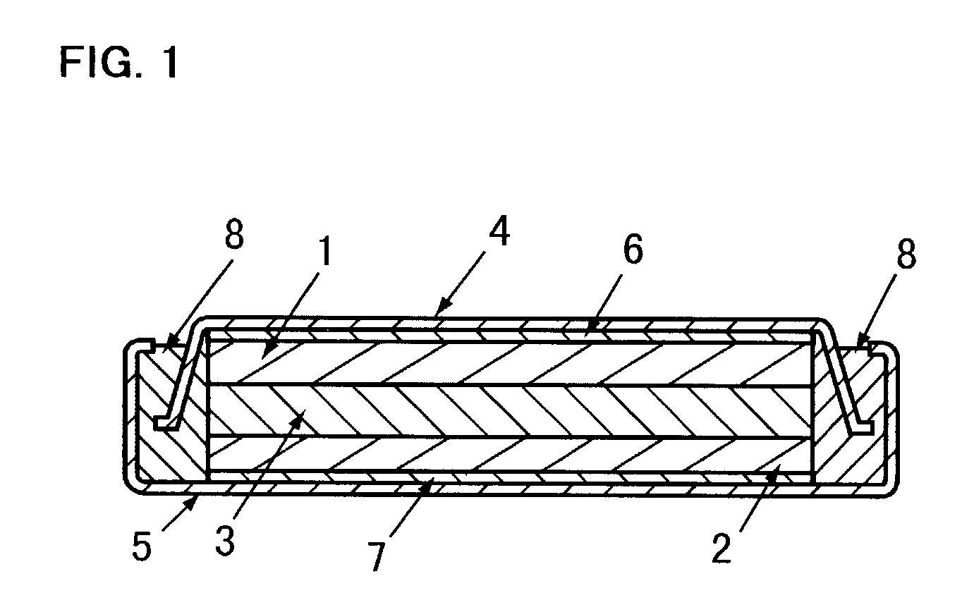
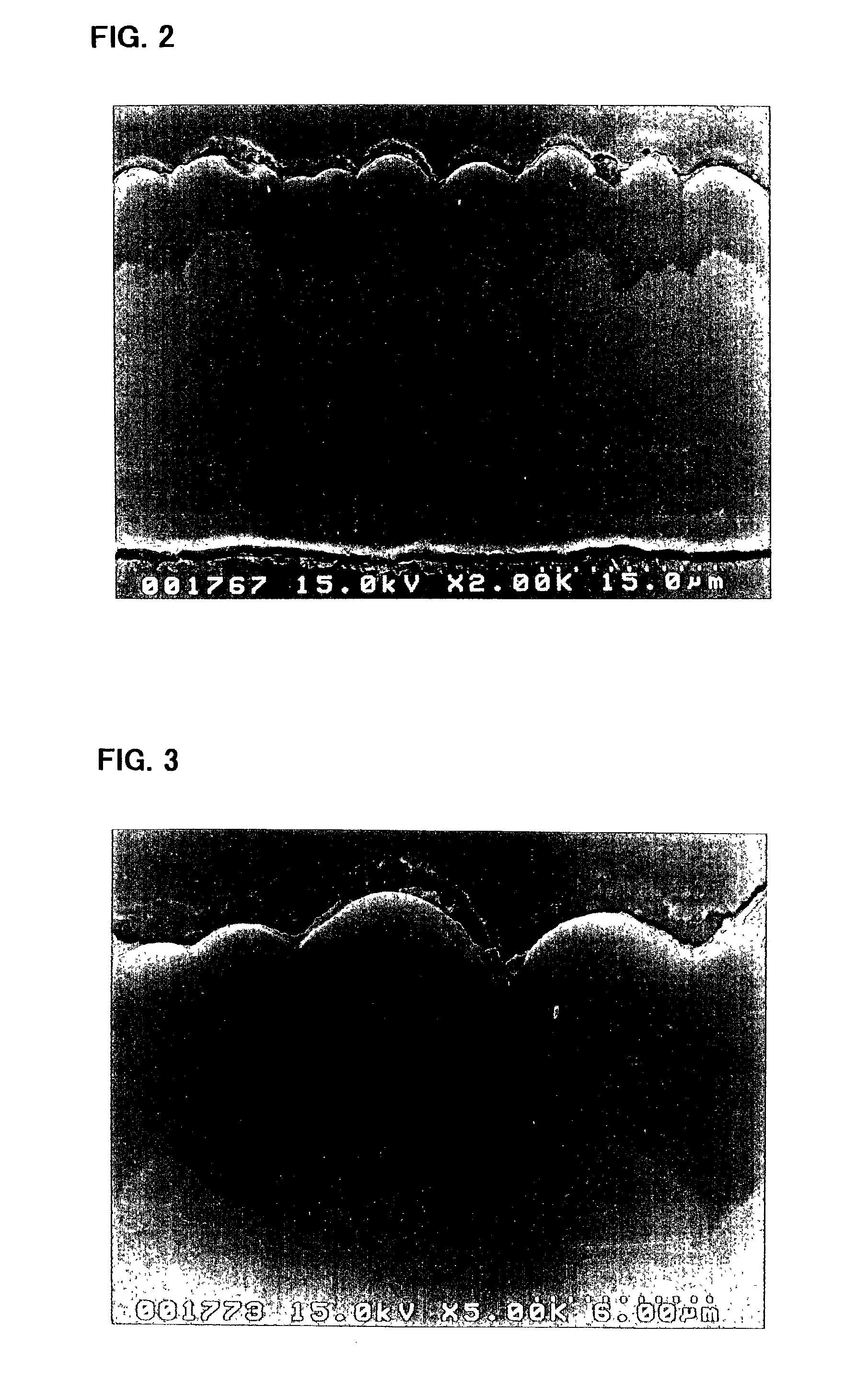
[0141]The electrode a3 incorporated in the battery A3 was viewed under an electron microscope to observe a condition of its silicon thin film. First, the electrode a3 in its state prior to being incorporated in the battery, i.e., before charge and discharge, was observed using a scanning electron microscope. FIGS. 2 and 3 are p...


PUM

PropertyMeasurementUnit
surface roughness Raaaaaaaaaaa
tensile strengthaaaaaaaaaa
thicknessaaaaaaaaaa

Abstract

An electrode for a rechargeable lithium battery which includes a thin film composed of active material that expands and shrinks as it stores and releases lithium, e.g., a microcrystalline or amorphous silicon thin film, deposited on a current collector, characterized in that said current collector exhibits a tensile strength (=tensile strength (N/mm2) per sectional area of the current collector material×thickness (mm) of the current collector) of not less than 3.82 N/mm.

Description

TECHNICAL FIELD[0001]The present invention relates to a novel electrode for a rechargeable lithium battery and also to a rechargeable lithium battery using the same.BACKGROUND ART[0002]The battery performance of rechargeable lithium batteries recently under intensive research and development, such as charge-discharge voltage, cycle life characteristics or storage characteristics, depends largely upon the types of the electrodes used. This has led to the attempts to better battery performance by improving electrode active materials.[0003]The use of metallic lithium for the negative active material, although possible to construct a battery with high energy density per weight and volume, presents a problem that the lithium deposited on charge grows into dendrite which could cause internal short-circuiting.[0004]Rechargeable lithium batteries are reported (Solid State Ionics, 113–115, p 57 (1998)) which use an electrode consisting of aluminum, silicon, tin or the like that is electroche...

Claims


Application Information

Patent Timeline
Patent Type & Authority Patents(United States)
IPC IPC(8): H01M4/02H01M4/38H01M4/70H01M4/13H01M4/131H01M4/134H01M4/139H01M4/1395H01M4/36H01M4/40H01M4/66H01M6/10H01M6/40H01M10/05H01M10/052H01M10/42H01M10/44H01M50/109
CPCH01M4/13H01M4/134H01M4/366H01M4/40H01M4/661H01M4/667H01M2/0207Y02E60/122H01M4/131H01M4/1395H01M4/38H01M4/405H01M4/485H01M4/525H01M4/70H01M6/40H01M10/052H01M10/0587H01M10/44H01M2010/4292H01M4/04H01M4/386H01M4/387Y02E60/10H01M50/109H01M4/64
Inventor IKEDA, HIROAKIFUJIMOTO, MASAHISAFUJITANI, SHINSHIMA, MASAKIYAGI, HIROMASATARUI, HISAKIKUROKAWA, HIROSHIASAOKA, KENJIMATSUTA, SHIGEKIDOMOTO, YOICHIOHSHITA, RYUJIKATO, YOSHIONAKAJIMAKUSUMOTO, YASUYUKI
Owner SANYO ELECTRIC CO LTD
Why Eureka
Try Eureka