Method for producing light-scattering structures on flat optical waveguides

a technology of optical waveguides and light-scattering structures, which is applied in the direction of optics, instruments, optical light guides, etc., can solve the problems of high cost, high cost, and high cost of known etching and lithographic methods, and achieves the effect of high cost, high cost, and high cos

Inactive Publication Date: 2007-03-20
SCHOTT AG
View PDF3 Cites 31 Cited by
  • Summary
  • Abstract
  • Description
  • Claims
  • Application Information

AI Technical Summary

Benefits of technology

[0011]It is one object of this invention to provide a method for producing light-scattering structures on flat optical waveguides, by which arbitrarily structured representations can be produced with low processing times and high throughput.
[0014]In accordance with this invention, it is possible to apply a fluid coating material, which sets after its application. Such a material can be simply processed, particularly in ink jet devices, wherein a lacquer, which can be hardened, a thermoplastic or thermosetting plastic material, or a glass paste can be used. The application of the light-scattering structures can be easily realized by imprinting with the aid of a computer-controlled contactless print head.
[0016]The coating material should be transparent or colored in the hardened or fixed state and have a refractive index which is approximately identical to the refractive index of the optical waveguide. It is thus possible to realize the easy coupling-out from the optical waveguide.
[0022]The application of the coating material can occur in one method step, and the application of the light-scattering centers in a subsequent method step. With this it is possible to vary the distribution of the light-scattering centers. For this purpose, the application of the light-scattering centers can occur computer-controlled in accordance with a predetermined distribution. It is thus possible to achieve an even coupling-out of the light, particularly in connection with differently shaped optical waveguides.

Problems solved by technology

For achieving uniform coupling-out of the light, the structures applied are very complex and can only be produced by “standard methods”, such as by screen-printing.
The known etching and lithographic methods are highly cost-intensive, particularly when structuring large surfaces, because it is necessary to use expensive photosensitive resists in large coating and exposure installations.
Such methods are also very time-consuming, because they are subject to long processing times.
However, the production of individual masks or punching tools by elaborate pre-preparation is only practical in connection with large numbers of pieces.
Here the achievable minimum resolution and the “dynamics” during simultaneous printing are much wider and greatly limited during simultaneous printing of very wide and very fine structures.
Also, a desired local variation of the compactness of the scattered light by different light-scattering structures or grid structures is difficult to realize.
Laser-supported methods for creating light-scattering structures, such as known interior etching by laser, wherein a structure is formed in the interior of a glass plate by lasers, are also expensive and have time-consuming applications.

Method used


Image

  • Method for producing light-scattering structures on flat optical waveguides
  • Method for producing light-scattering structures on flat optical waveguides
  • Method for producing light-scattering structures on flat optical waveguides

Examples


Embodiment Construction

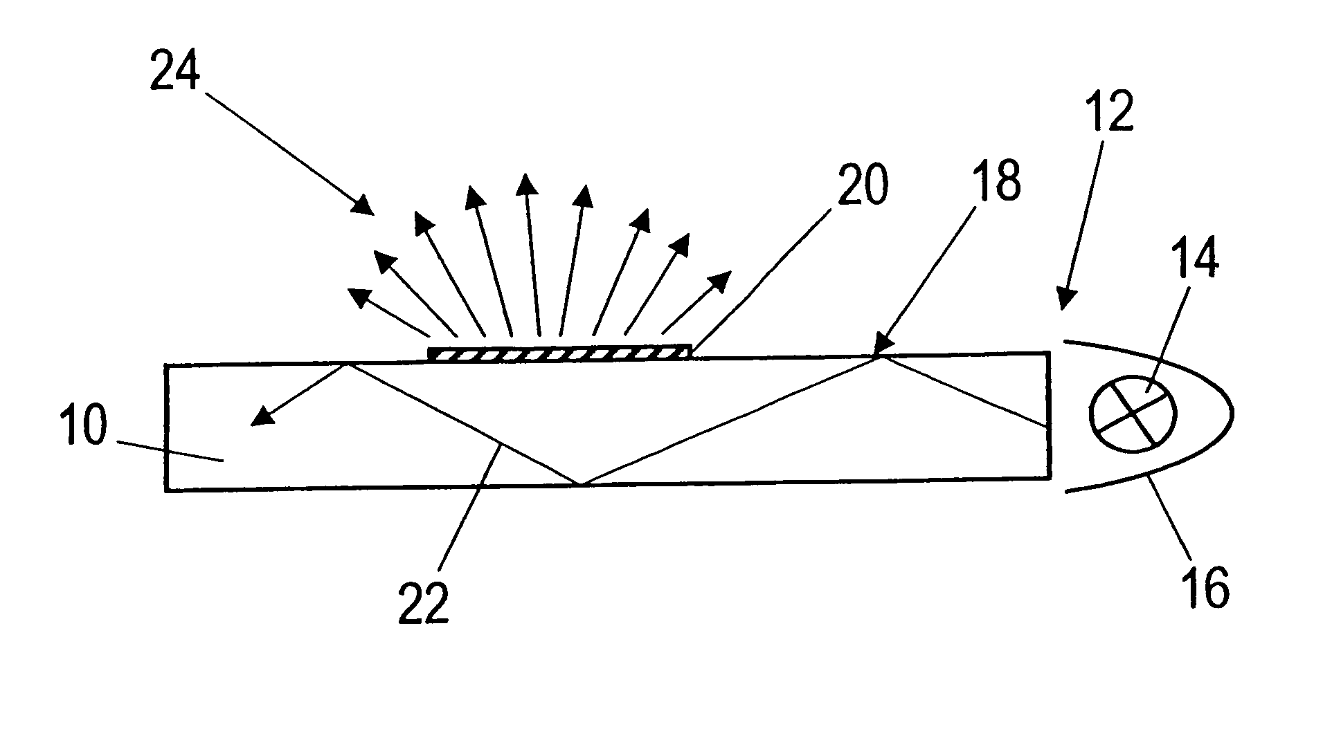
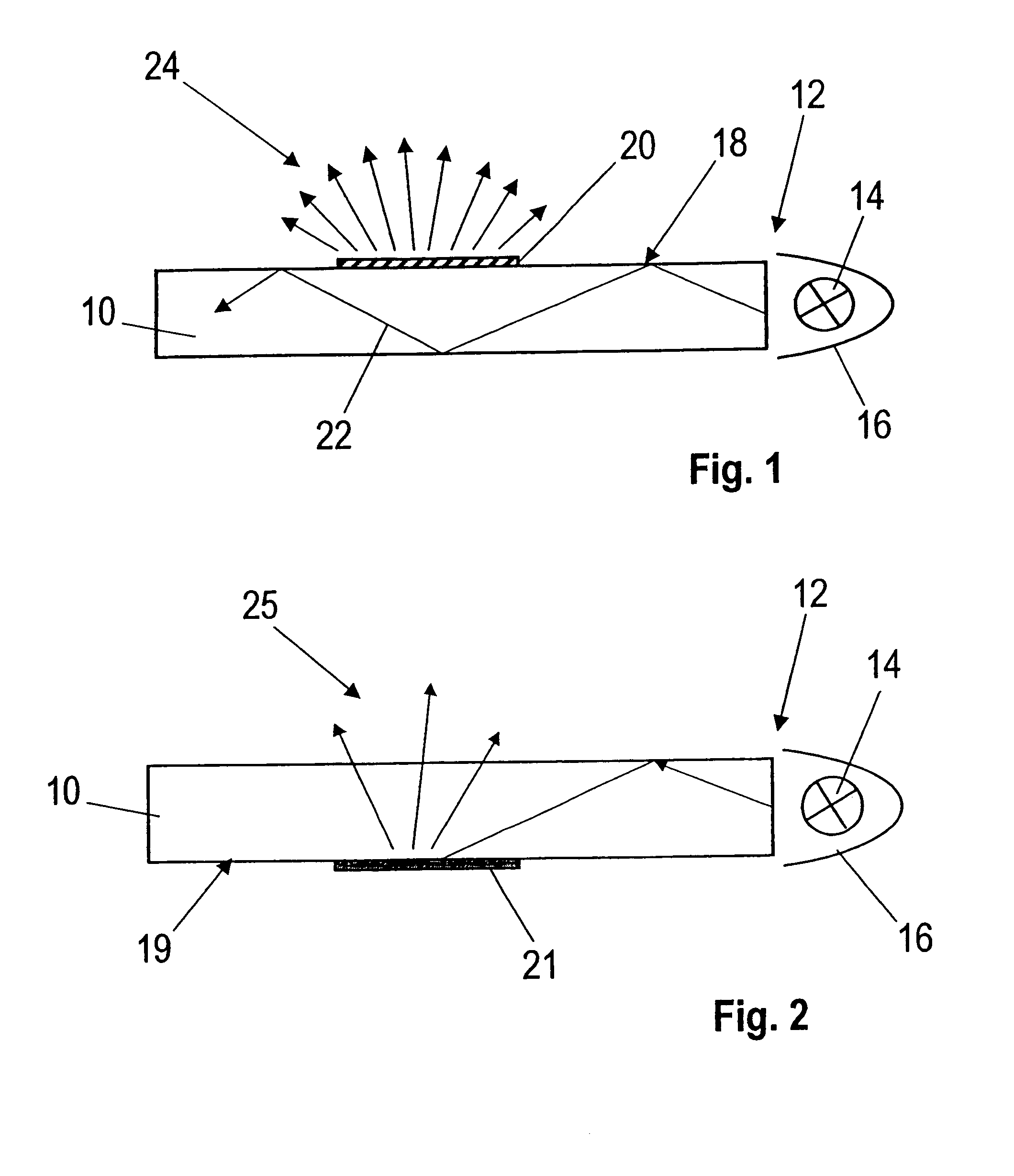
[0030]A plate 10 made of glass or a transparent plastic material is shown in a schematic plan view and in section in FIG. 1, having a right edge area 12 in which the light from a lamp 14 is coupled. A mirror device 16 is arranged at the lamp 14, which focuses the light from the lamp 14 to the edge area 12 and shades the space facing away from the optical waveguide 10. A light-scattering structure 20 is attached to the upper outer surface 18 of the plate 10, wherein the light is coupled out toward the top. The coupled-in light 22 is conducted inside the plate 10 by total reflection. The light is coupled out of the plate 10 acting as an optical waveguide in the form of scattered light 24 at the light-scattering structure 20.

[0031]FIG. 2 shows a similar arrangement where one difference from the arrangement shown in FIG. 1 is that a light-scattering structure 21 is attached to the lower outside surface 19 of the plate 10. In this case, the light is coupled out upward from the plate 10 a...


PUM


Abstract

A method for producing light-scattering structures on flat optical waveguides into which light can be coupled for making the light-scattering structures visible. The light-scattering structures are applied to a surface of the optical waveguide in accordance with a predetermined arrangement prescription. The light-scattering structures are applied directly to the optical waveguide with a non-impact method. The application of the light-scattering structures can occur by imprinting with a computer-controlled, contactless-operating print head or by electro-photographic coating.

Description

BACKGROUND OF THE INVENTION[0001]1. Field of the Invention[0002]This invention relates to a method for producing light-scattering structures on flat optical waveguides, into which light can be coupled for making the light-scattering structures visible, wherein the light-scattering structures are applied to a surface of the optical waveguide in accordance with a predetermined arrangement prescription.[0003]2. Discussion of Related Art[0004]It is known to employ “free-floating” letters and representations for advertising purposes or as indicating signs. Such light-scattering structures permit individual designer solutions for illuminated monochromatic or colored indicating means.[0005]It is known to engrave or etch symbols or letters into plates made of glass or transparent plastic. Such structures can also be applied in the plate interior with laser techniques. The structures become visible, or are excited to glow, by illuminating the plates by coupling light in via the plate edges. ...

Claims


Application Information

Patent Timeline
Patent Type & Authority Patents(United States)
IPC IPC(8): G02B6/12G02B6/10G02B6/26G02B6/34G02B6/42F21V8/00
CPCG02B6/0065G02B6/0043
Inventor SCHULTHEIS, BERNDENGELMANN, HARRYOTTERMANN, CLEMENS
Owner SCHOTT AG
Why Eureka
Try Eureka