Tin alloy electroplating system

a technology of tin alloy and electroplating system, which is applied in the direction of electrolysis components, electrolysis processes, cells, etc., can solve the problems of tin plating suffering from a significant drawback, undesirable formation of spontaneous latent whisker, and ductile finish that can scratch or mar easily, so as to minimize and/or eliminate latent whiskering, the effect of alleviating disposal, environmental and health concerns

Active Publication Date: 2007-03-27
COVENTYA INC
View PDF17 Cites 37 Cited by
  • Summary
  • Abstract
  • Description
  • Claims
  • Application Information

AI Technical Summary

Benefits of technology

[0005]The present invention involves plating tin alloys while minimizing and / or eliminating latent whiskering. The tin alloys alleviate disposal, environmental, and health concerns since they are lead free. The tin alloy plating system permits the employment of working tin anodes without the danger of immersion plating of the alloy material thereon. In many instances, the tin alloy plating system permits plating tin alloys without the need of complexing and / or chelating agents, further alleviating disposal, environmental, and health concerns associated with metal plating systems. Since working tin anodes may be employed as a source of tin in the tin alloy plating systems, significant cost reductions are achieved compared to plating systems that use liquid based tin salts as a tin source. The resultant tin alloys formed in accordance with the present invention have desirable characteristics including one or more of lack of latent whiskering, relatively high tin content, lead free alloys, excellent solderability, excellent lubricity, excellent electrical conductivity, corrosion resistance, excellent leveling, excellent ductility, lack of pinholes, and controllable thickness.

Problems solved by technology

While tin does not tarnish easily, tin is a soft, ductile finish that can scratch or mar easily.
Unfortunately, tin plating suffers from a significant drawback, the undesirable formation of spontaneous latent whiskers.
In some applications using tin plating, whiskers are not functionally noticed and therefore harmless.
However, in other applications, such as closely spaced electronic circuits, whiskers undermine the operational function of devices employing a tin plating product.
Due to disposal, environmental, and health concerns, deposits that contain lead, as well as the general use of lead, are no longer desirable.

Method used


Image

  • Tin alloy electroplating system
  • Tin alloy electroplating system
  • Tin alloy electroplating system

Examples


Embodiment Construction

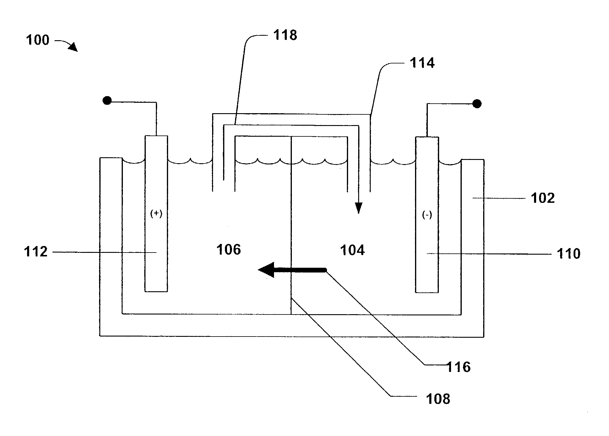
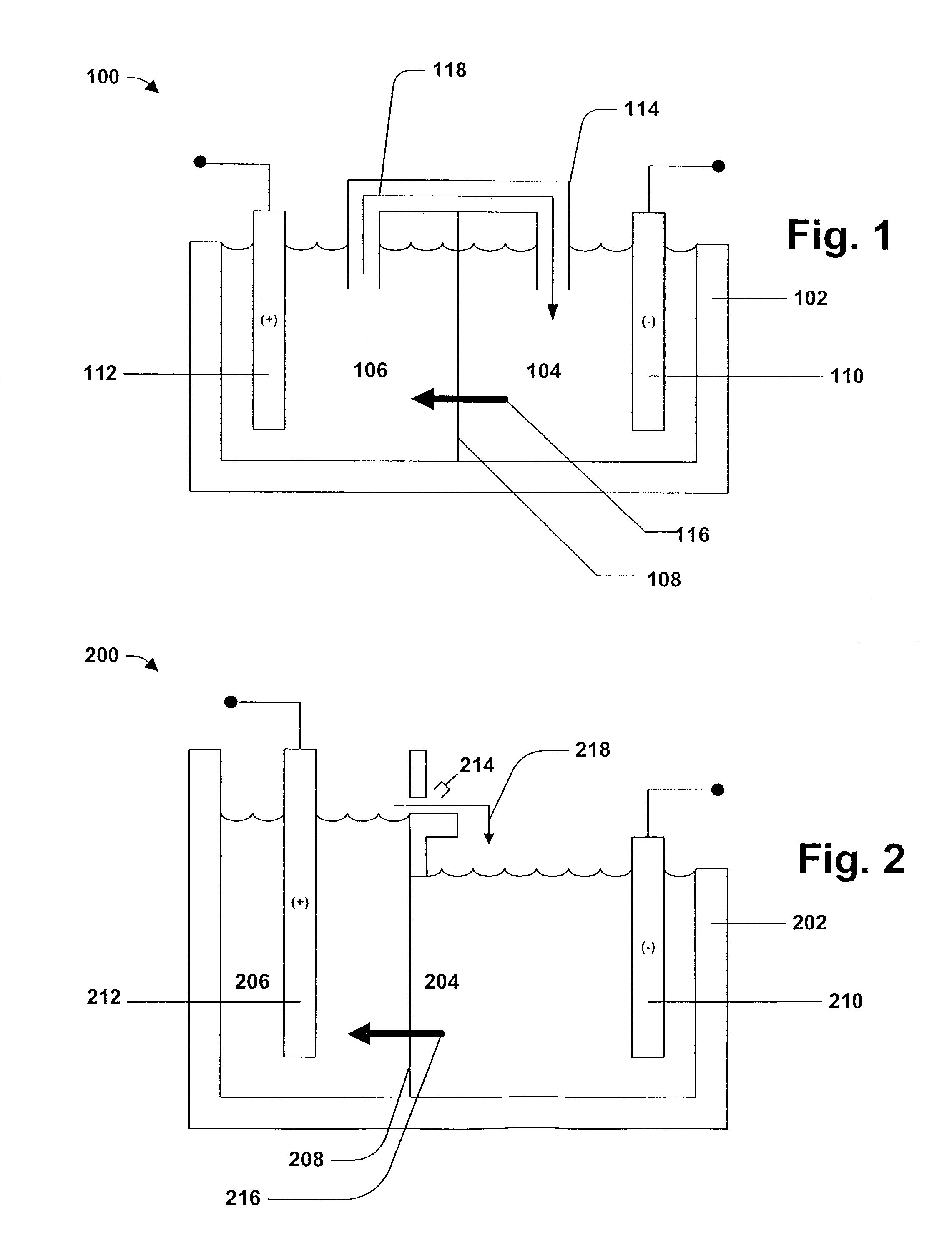
[0011]The present invention can be employed for tin alloy electroplating. Generally speaking, electroplating involves metal in ionic form migrating in solution from a positive to a negative electrode. An electrical current passing through the solution causes substrates at the cathode to be coated by the metal (tin and alloy metal(s)) in solution. That is, in most embodiments, the substrate to be plated is the cathode.

[0012]Referring to FIG. 1, the tin alloy plating system 100 includes a power source (not shown) for providing current to an electrochemical cell 102 containing an anolyte compartment 106 and a catholyte compartment 104 separated by a selective membrane 108 (and this general arrangement may be repeated one or more times to provide electrochemical cells with a plurality of anolyte compartments 106, catholyte compartments 104, and selective membranes 108). The anolyte compartment 106 contains an anode 112 and an aqueous anolyte and the catholyte compartment 104 contains a ...


PUM

PropertyMeasurementUnit
diameteraaaaaaaaaa
diameteraaaaaaaaaa
current carrying capacityaaaaaaaaaa

Abstract

Disclosed are systems and methods of plating a tin alloy in an efficient, economical, and environmentally friendly manner. An electrochemical cell containing an anolyte compartment and a catholyte compartment separated by a selective membrane is employed. The selective membrane prevents ionic metals from migrating from the catholyte compartment to the anolyte compartment. A conduit may be employed in the electrochemical cell to permit one way flow of anolyte to the catholyte compartment thereby replenishing tin to the catholyte compartment.

Description

FIELD OF THE INVENTION[0001]The present invention generally relates to plating a tin alloy on a substrate. In particular, the present invention relates to systems and methods for electroplating tin alloys without the occurrence of whiskering.BACKGROUND OF THE INVENTION[0002]Tin plating is known. Tin has many desirable attributes as a plated finish including solderability, lubricity, good electrical conductivity, and corrosion resistance. Tin is a silver-colored, ductile metal whose major application is to impart solderability to otherwise unsolderable base metals. Tin has generally good covering characteristics over a wide range of shapes. While tin does not tarnish easily, tin is a soft, ductile finish that can scratch or mar easily. Tin is reported to be non-toxic and non-carcinogenic and thus is approved for food container and food contact applications.[0003]Unfortunately, tin plating suffers from a significant drawback, the undesirable formation of spontaneous latent whiskers. W...

Claims


Application Information

Patent Timeline
Patent Type & Authority Patents(United States)
IPC IPC(8): C25D3/30C25D17/00C25D3/32C25C7/00C25D3/56C25D3/58C25D3/60C25D21/18
CPCC25D21/18
Inventor BOKISA, SR., GEORGE S.ECKLES, WILLIAM E.FRISCHAUF, ROBERT E.
Owner COVENTYA INC
Why Eureka
Try Eureka