Composite webs and closure systems

a technology of closure system and composite web, which is applied in the field of composite web, can solve the problems of reducing the breathability of the web, adding cost and weight to the web, and reducing the rigidity of the entire surface of the web, so as to control the shape, spacing and volume of one or more polymeric structures

Inactive Publication Date: 2007-03-27
3M INNOVATIVE PROPERTIES CO
View PDF77 Cites 94 Cited by
  • Summary
  • Abstract
  • Description
  • Claims
  • Application Information

AI Technical Summary

Benefits of technology

[0023]Another potential advantage of the present invention is the opportunity to provide polymer structures that include surface features formed on their upper surfaces (i.e., the surfaces facing away from the substrate). The surface features may be, e.g., stems, hooks, pyramids, channels, indicia (alphanumeric or otherwise), etc. and may provide additional functionality such as, e.g., mechanical fastening, etc. These surface features may be provided in an integral process step at the same time as formation and transfer of the polymer structures themselves (as opposed to a separate, subsequent process step). Alternatively, though, the surface features could be provided after formation of the polymer structures.
[0024]Another potential advantage is the ability to control the shape, spacing, and volume of the one or more polymeric structures. In some instances, it may be preferred that a plurality of polymeric structures be provided on the first major surface of the substrate, with each of the polymeric structures being discrete polymeric structures (i.e., not connected to each other by the thermoplastic composition transferred to the substrate).
[0025]Another potential advantage of the present invention may be found in the ability to provide a thin base film between thicker thermoplastic composition structures. The thicker thermoplastic composition structures are attached to the substrate, but the base film may or may not be attached to the substrate. The base film may be, e.g., attached to the substrate by adhesives.
[0026]Another potential advantage of the methods of the present invention is the ability to provide one or more polymeric structures that extend for the length of the substrate (while preferably not being formed over the width of the substrate, i.e., the polymeric structures are not coextensive with the major surface of the substrate).
[0027]Another potential advantage of the methods of the present invention is the ability to provide different thermoplastic compositions in different areas across the width of the substrate, such that some polymeric structures may be formed of one thermoplastic composition, while other polymeric structures are formed of a different thermoplastic composition.
[0028]Yet another potential advantage of the methods of the present invention is the ability to provide one or more polymeric structures on both major surfaces of a substrate. The polymeric structures on the opposing major surfaces may be formed with the same or different structures as desired.

Problems solved by technology

Such approaches can, however, add cost and weight to the web, as well as stiffness over the entire surface of the web—even in those areas that do not require reinforcement.
Furthermore, reinforcing layers that are coextensive with the web may also reduce its breathability.
The handling and attachment of such discrete pieces can, however, be problematic, by potentially reducing throughput, causing waste (where the discrete pieces are not securely attached), requiring precise registration or location on the web, requiring the use of adhesives or other bonding agents, etc.
The discrete pieces may also present relatively sharp edges that may be the source of irritation or discomfort.
The irritation or discomfort can be exacerbated because the reinforcing pieces are typically located on the surface of the substrate.
Although elasticity may be beneficial in a variety of different applications, it may raise issues in manufacturing.
The manufacture of such composite articles may be problematic in that secure attachment of the elastic components may be difficult to achieve and / or maintain.
Further, the cost and difficulty of providing and attaching separate elastic components may be relatively high.
The handling and attachment of separate elastic components can reduce throughput, cause additional waste (where the separate components are not securely attached), etc.
Such an approach may add costs associated with providing a coextensive elastic layer or layers.
Further, many elastic materials are not breathable.
Such additional processing does, however, add to the cost of producing the elastic laminate backing.
Another potential disadvantage of elastic laminate backings is that it may be difficult to provide any adjustment of the elastic recovery forces generated in different portions of the backing.

Method used


Image

  • Composite webs and closure systems
  • Composite webs and closure systems
  • Composite webs and closure systems

Examples


example 1

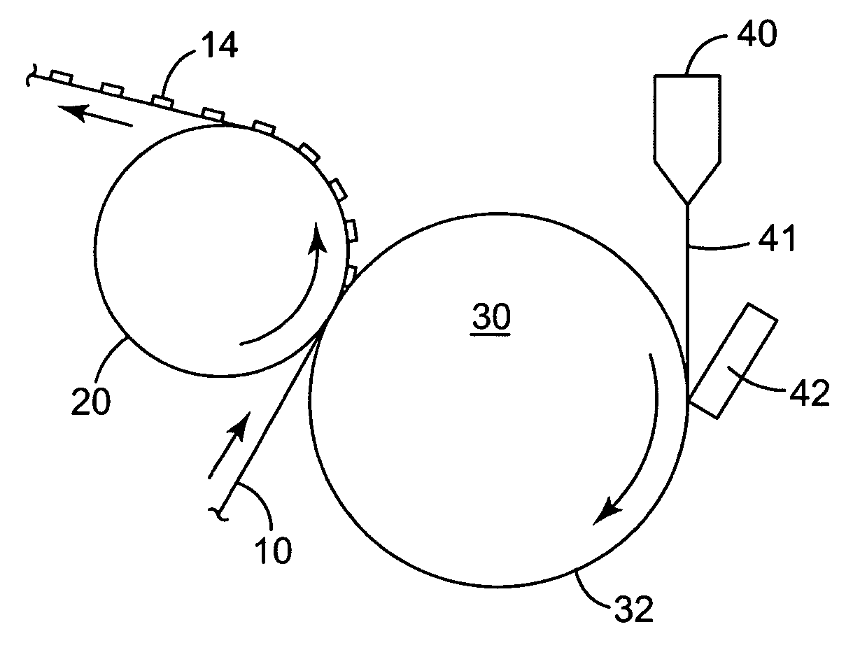
[0229]A composite web was produced using a system similar to that shown in FIG. 15. A 40 mm diameter twin screw extruder fitted with a gear pump was used to deliver a molten polypropylene polymer (7C05N, Huntsman) at a melt temperature of approximately 246° C. to a die. The die was positioned such that a film of molten polymer was extruded vertically downward into the interface region of a heated doctor blade and a cooled forming roll.

[0230]The doctor blade was forced against the forming roll with a pressure of 93 pounds per lineal inch (163 Newtons per lineal cm) (a pressure which allowed the molten polymer to create a gap between the blade and the roll which defined the thickness of the base film). The doctor blade was maintained at a temperature of 246° C. and the forming roll was maintained at a temperature of 30° C. by circulating cooled oil through the interior of the roll.

[0231]The exterior surface of the forming roll was machined using a computer controlled milling machine t...

example 2

[0234]A composite web was produced using a system similar to that shown in FIG. 15. A 40 mm diameter twin screw extruder fitted with a gear pump was used to deliver a molten polymer consisting of a styrene-ethylenebutylene-styrene block copolymer (KRATON G-1657) at a melt temperature of approximately 246° C. to a die. The die was positioned such that a film of molten polymer was extruded vertically downward into the interface region of a heated doctor blade and a cooled forming roll. The doctor blade was maintained at a temperature of 246° C. and the forming roll was maintained at a temperature of 30° C. by circulating cooled oil through the interior of the roll. The doctor blade was held against the forming roll with a pressure of 450 pounds per lineal inch (788 Newtons / lineal cm).

[0235]The exterior surface of the forming roll was machined using a computer controlled milling machine to have a series of six (6) different areas arranged around the periphery of the roll. Each of these...


PUM

PropertyMeasurementUnit
temperatureaaaaaaaaaa
lengthsaaaaaaaaaa
angleaaaaaaaaaa

Abstract

Composite webs having one or more polymeric structures located on a substrate, closure systems comprising composite webs, and methods of attaching articles are disclosed. The polymeric structures are formed using thermoplastic compositions and are attached to a surface of a substrate. The polymeric structures include an area that is attached to the substrate and a detached area that is not attached to a surface of a substrate.

Description

RELATED APPLICATION[0001]This application is a continuation-in-part of U.S. patent application Ser. No. 10 / 387,699, filed Mar. 13, 2003, which is incorporated herein by reference in its entirety.FIELD OF THE INVENTION[0002]The present invention relates to composite webs that include one or more polymeric structures on a substrate, as well as methods and systems for manufacturing the composite webs.BACKGROUND[0003]The manufacture of articles formed of webs that require some reinforcement to withstand forces experienced during use are known. In many cases, reinforcement is simply provided over the entire substrate or web. Such approaches can, however, add cost and weight to the web, as well as stiffness over the entire surface of the web—even in those areas that do not require reinforcement. Furthermore, reinforcing layers that are coextensive with the web may also reduce its breathability.[0004]To address some of these issues, smaller pieces of reinforcing materials may be attached t...

Claims


Application Information

Patent Timeline
Patent Type & Authority Patents(United States)
IPC IPC(8): B29C41/26B29C41/44B29C41/46A44B18/00B29C43/22B29C43/28B32B3/02B32B3/28B32B5/04B32B7/02
CPCA44B18/0049A44B18/0061B29C43/222B29C43/28B32B7/02B32B3/02B32B3/28B32B5/04B29L2031/729Y10T428/249991Y10T428/249955B32B2274/00B32B27/12B32B37/025B32B2307/51
Inventor JACKSON, BYRON M.WOOD, LEIGH E.ALBERG, RANDALL L.BECKER, DENNIS L.PAVLIS, ROGER D.
Owner 3M INNOVATIVE PROPERTIES CO
Why Eureka
Try Eureka