
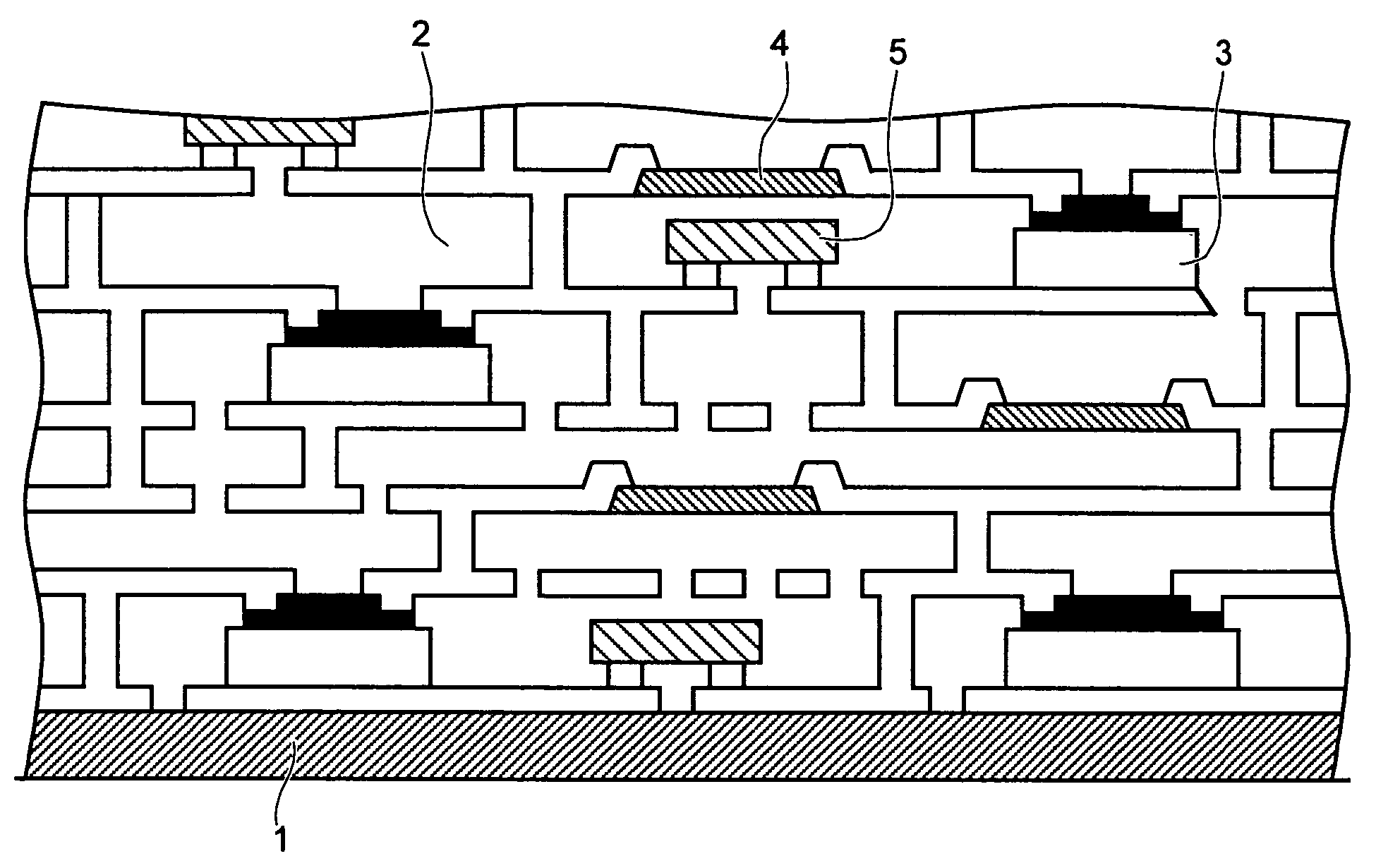
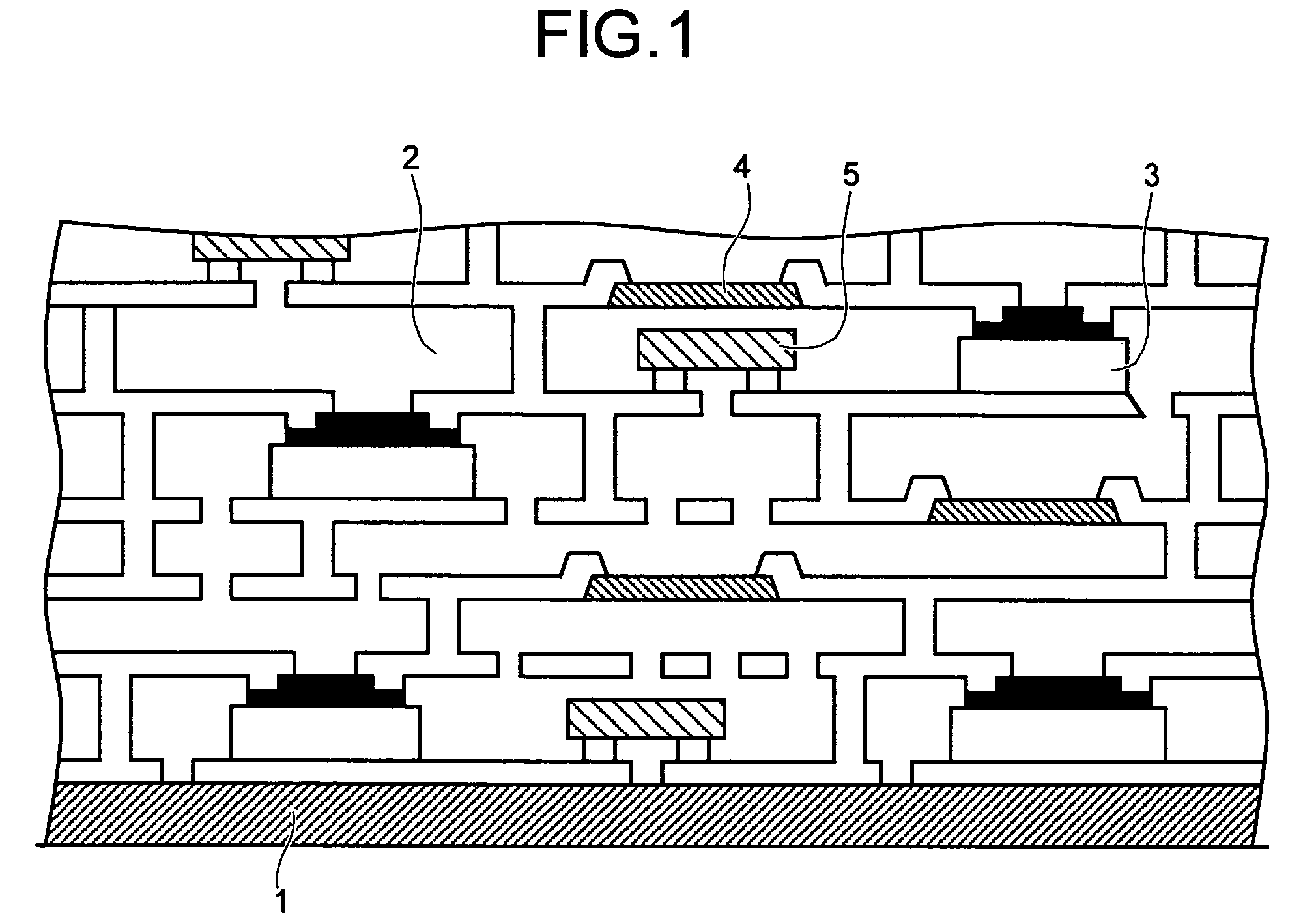
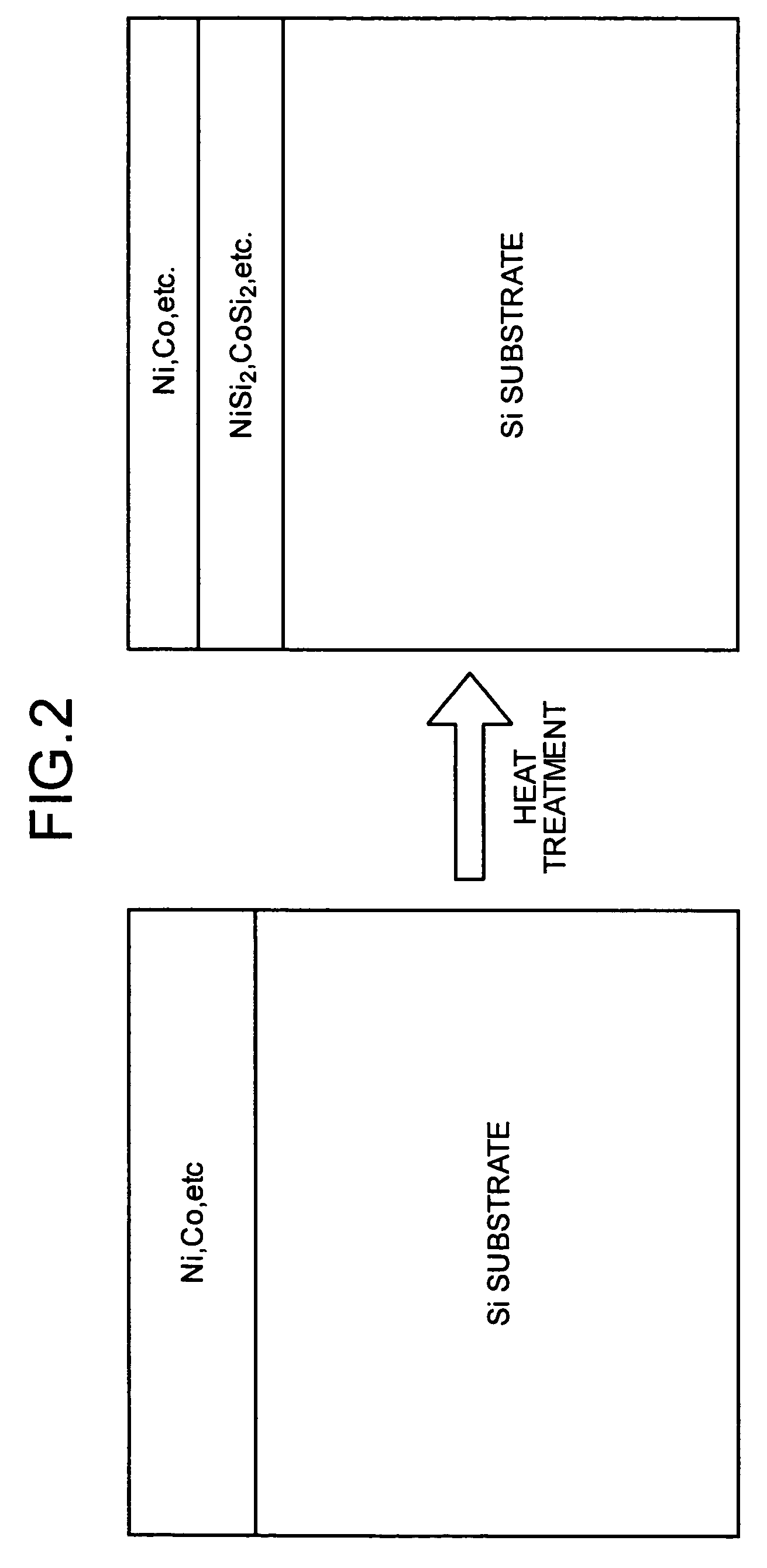
Thin film capacitor, high-density packaging substrate incorporating thin film capacitor, and method for manufacturing thin-film capacitor

a technology thin film capacitor, which is applied in the manufacture of capacitors, fixed capacitor details, fixed capacitors, etc., can solve the problems of not having a sufficiently thin size available in wiring in the packaging substrate, limiting the freedom of design of high-density packaging substrates, and not achieving the incorporation of capacitors in packaging substrates. achieve the effect of sufficient capacitan

Inactive Publication Date: 2007-03-27
WASEDA UNIV +2
View PDF8 Cites 25 Cited by
  • Summary
  • Abstract
  • Description
  • Claims
  • Application Information

AI Technical Summary

Benefits of technology

The present invention provides a thin-film capacitor that can be incorporated into a packaging substrate without deteriorating its electric properties and size feature. The thin-film capacitor has a high-dielectric-constant layer, an upper electrode layer, and a lower electrode layer. The capacitor can be connected to a wiring layer on the substrate as a passive component, and the substrate can be made thin by mechanical and chemical polishing. The thin-film capacitor can be incorporated into a high-density packaging substrate and can be connected to the substrate using wire bonding techniques or other methods. The material composing the electrodes can be metals or conductive metal oxides, and the conductive material for filling the contact holes can be copper or aluminum. The invention also provides a method for manufacturing the thin-film capacitor.

Problems solved by technology

When the bypass capacitor is mounted outside the board, mounting position of the capacitor on the packaging substrate will be limited, which will restrict the freedom of designing a high-density packaging substrate.
However, a capacitor having a sufficiently thin size available in wiring in the packaging substrate has not yet been obtained so far, and incorporation of the capacitor in the packaging substrate has not thus been achieved.
Generally, a ferroelectric material exhibits a high dielectric loss and may cause problems as to its property for use in high frequency.
However, it is difficult to reduce the thickness of a ceramic dielectric (film) in the screen printing method as described above.
If the conventional capacitor is forcedly embedded, a part of the packaging substrate below the capacitor has to be concaved, and the via has to be vertically extended to expand the gap between an upper wiring layer and a lower wiring layer, which would inhibit thinning of the packaging substrate and result in a unsatisfactory product in terms of technology and cost.
Particularly, great restrictions will be imposed on a bypass capacitor which has to be disposed near the power supply pin of an IC chip.

Method used


Image

  • Thin film capacitor, high-density packaging substrate incorporating thin film capacitor, and method for manufacturing thin-film capacitor
  • Thin film capacitor, high-density packaging substrate incorporating thin film capacitor, and method for manufacturing thin-film capacitor
  • Thin film capacitor, high-density packaging substrate incorporating thin film capacitor, and method for manufacturing thin-film capacitor

Examples


synthesis example 1

[0120]A composition example of a sol-gel coating solution for forming BaxSr1−xTiO3 (x=0.6) will be described.

[0121]A solution of barium isopropoxide was diluted in advance to a concentration of 0.5 mol / kg with propylene glycol monomethyl ether, and a titanium isopropoxide solution was also diluted in advance to a concentration of 0.5 mol / kg with propylene glycol monomethyl ether. The solutions each of which in an amount corresponding to 1 mol were mixed and stirred for 30 minutes to be uniform.

[0122]Subsequently, a solution of pure water diluted with 20 times weight ratio of propylene glycol monomethyl ether was added dropwise to the mixture solution of barium and titanium under stirring, and stirred for one hour. The added amount of H2O was 3.5 times molar ratio of the total molar amount of the barium and titanium. By adjusting the amount of propylene glycol monomethyl ether added at the beginning, the concentration in terms of BaTiO3 was adjusted to 0.15 mol / kg. Accordingly, a BaT...

synthesis example 2

[0125]An SrTiO3 solution (STO solution) having a concentration of 0.15 mol / kg in terms of SrTiO3 was obtained in the same manner described in Synthesis Example 1.

synthesis example 3

[0126]An SrBi2Ta2O9 solution (hereinbelow referred to as SBT solution) was obtained in accordance with the method described below. Tantalum ethoxide in an amount corresponding to 2 mol, bismuth butoxide in an amount corresponding to 2.1 mol, and strontium isopropoxide in an amount corresponding to 0.9 mol were mixed with propylene glycol monomethyl ether. The solution was stirred for two hours at room temperature for uniform mixing. Subsequently, 3 mol of ethyl acetoacetate was added and the solution was subjected to heat stirring at 80° C. for two hours. Then, 1 mol of propylene glycol was added thereto and the solution was stirred for one hour at room temperature. Then, 2 mol of water was added dropwise to the solution while stirring, and after finishing the addition, the solution was stirred at room temperature for two hours, to prepare an SBT solution containing 6.5 wt. % of solid metal oxides.

(Evaluation of XRD Measurement)

[0127]Each of the solutions prepared in Synthesis Examp...


PUM

PropertyMeasurementUnit
thicknessaaaaaaaaaa
thicknessaaaaaaaaaa
thicknessaaaaaaaaaa

Abstract

A capacitor capable of being incorporated into a packaging substrate, which capacitor includes a high-dielectric-constant layer, and an upper electrode layer and a lower electrode layer sandwiching the high-dielectric-constant layer from the upper side and the lower side. A packaging substrate containing the capacitor, and a method for producing the same are also provided.

Description

BACKGROUND OF THE INVENTION[0001]1) Field of the Invention[0002]The present invention relates to a thin-film capacitor, a high-density packaging substrate incorporating the thin-film capacitor, and a method for manufacturing the thin-film capacitor, which enable integral incorporation of electronic devices such as passive components L (inductors and coils), C (condenser or capacitor), and R (resistor), and active components IC (semiconductor) whereby a printed board may be downsized and the degree of density thereof may be intensified, and therefore suitable for realizing a high density packaging substrate which incorporates electronic components.[0003]2) Description of the Related Art[0004]As well known, circuits for multi-layer printed wiring boards have recently been miniaturized and multi-layered, for downsizing and increasing density of the printed boards. In such a multi-layer printed wiring board, requisite components such as active components such as IC, and passive componen...

Claims


Application Information

Patent Timeline
Patent Type & Authority Patents(United States)
IPC IPC(8): H01G4/06H01G2/00H01G4/12H01G4/008H01G4/30H01G4/33H01G13/00H01G13/06H01L21/822H01L27/04H05K1/16H05K3/38H05K3/46
CPCH01G4/33H01G13/006H05K1/162H01G4/1227H01G4/008Y10T29/49155H05K3/388H05K2201/0175H05K2201/0179H05K2203/016Y10T29/42Y10T29/49169Y10T29/43Y10T29/49147Y10T29/435Y10T29/49165
Inventor OSAKA, TETSUYAKOIWA, ICHIROHASHIMOTO, AKIRASATO, YOSHIMI
Owner WASEDA UNIV
Learn More