
Rare earth alloy sintered compact and method of making the same

a technology of rare earth alloy and compact, which is applied in the direction of magnetic materials, inductance/transformer/magnet manufacturing, magnetic bodies, etc., can solve the problems of insufficient magnetization of insufficiently magnetized magnets, difficult to apply a sufficiently high strength magnetizing field to sintered compact, and easy oxidization of fe—b based alloy powders

Inactive Publication Date: 2007-04-10
HITACHI METALS LTD
View PDF21 Cites 11 Cited by
  • Summary
  • Abstract
  • Description
  • Claims
  • Application Information

AI Technical Summary

Benefits of technology

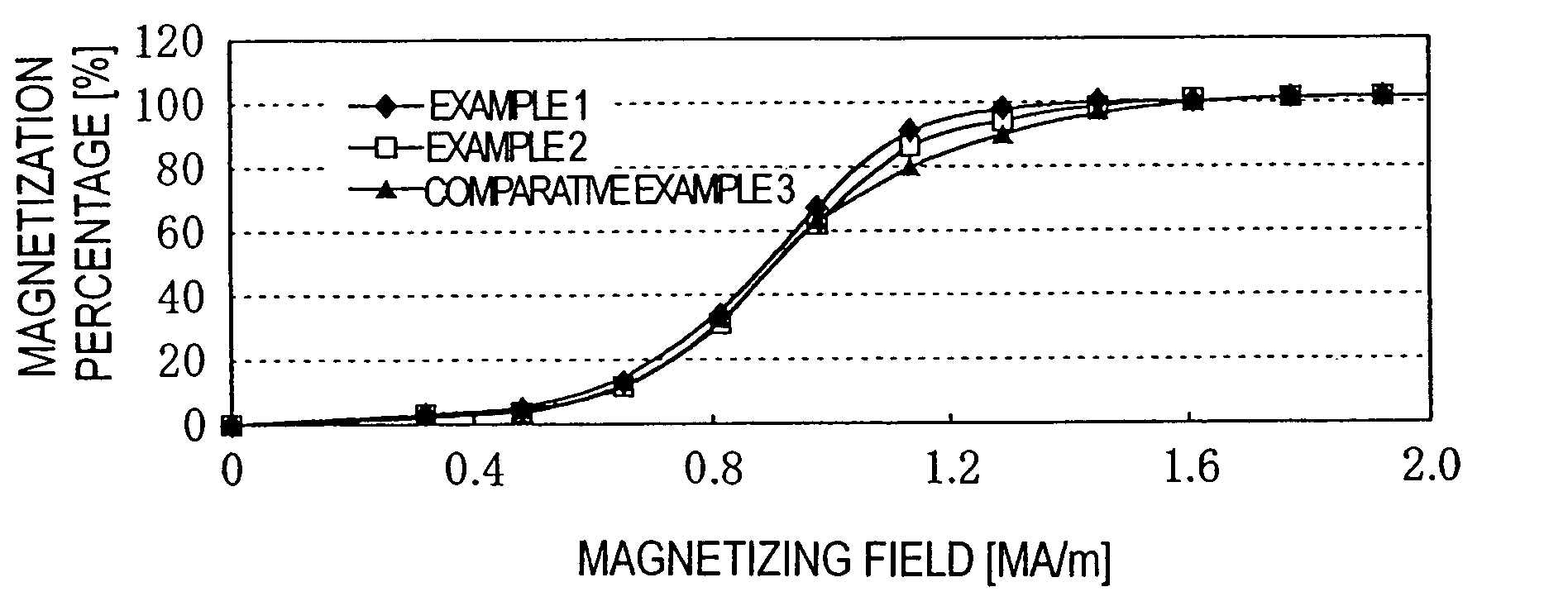
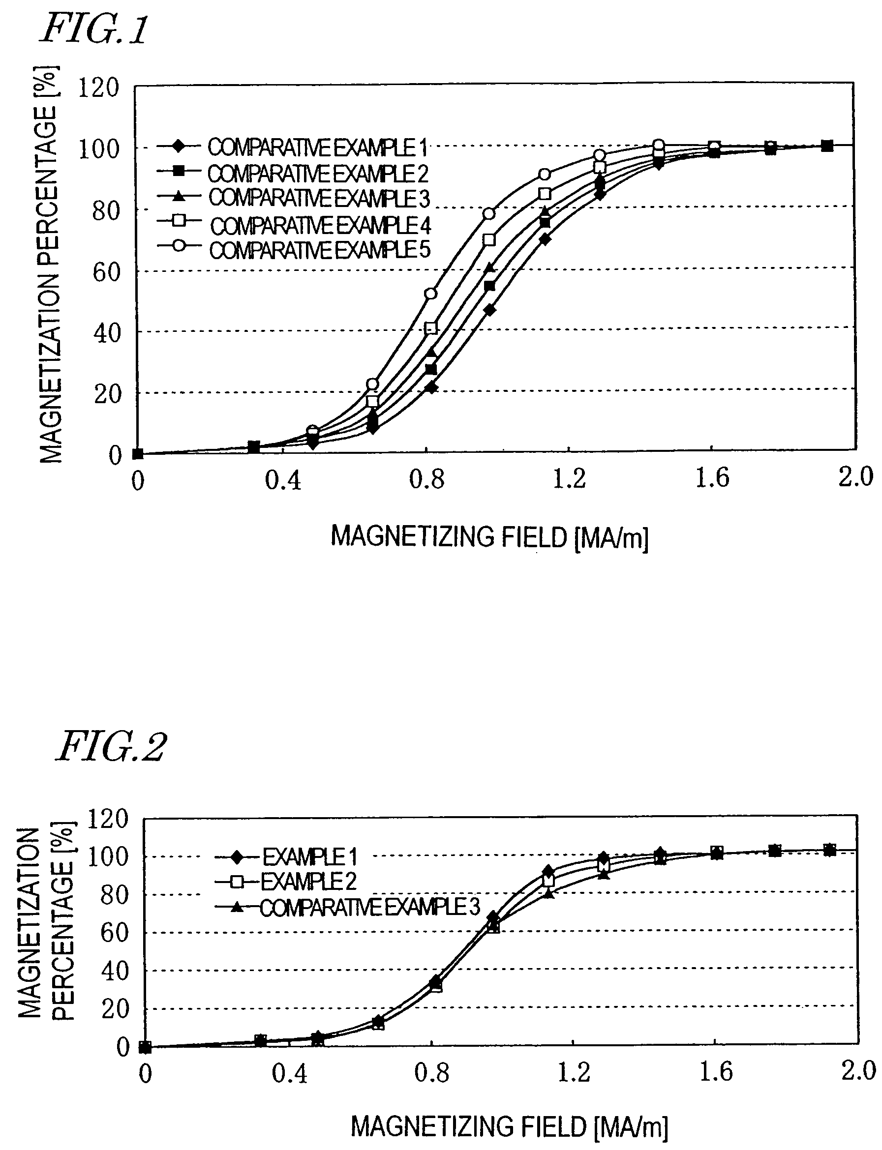
The present invention provides a rare earth alloy sintered compact with a main phase that has an improved magnetization response when subjected to a lower magnetizing field. The rare earth alloy sintered compact has a composition represented by (LR1-xHRx)2T14A, where T is either Fe alone or a mixture of Fe and at least one transition metal element other than Fe, A is either boron alone or a mixture of boron and carbon, LR is at least one light rare earth element, HR is at least one heavy rare earth element, and 0<x<1. The rare earth alloy sintered compact also includes crystal grains with multiple main phases of different compositions. The technical effect of this invention is to provide a rare earth alloy sintered compact with improved magnetic properties that can be used in various applications.

Problems solved by technology

An R—Fe—B based alloy powder is easily oxidizable, which is disadvantageous.
However, when the “composition of a rare earth alloy powder” is in question, the composition is that of the rare earth alloy powder itself, not the combination of the powder and the oxide film or lubricant coating.
In that situation, it is sometimes difficult to apply a magnetizing field with a sufficiently high strength to the sintered compact.
An insufficiently magnetized magnet will exhibit inferior magnetic properties.
Also, even if those other magnetic properties do not deteriorate, it is difficult to mass-produce the magnets because the elements to be added or substituted are rare and expensive.
However, once the average crystal grain size is decreased, the magnetization characteristic of the sintered compact will deteriorate disadvantageously.
Furthermore, once the particle size of the powder to be sintered is decreased, the powder becomes less easy to handle and shows a lower degree of orientation (i.e., degree of crystallographic orientation) during the compaction process.

Method used


Image

  • Rare earth alloy sintered compact and method of making the same
  • Rare earth alloy sintered compact and method of making the same
  • Rare earth alloy sintered compact and method of making the same

Examples


examples

[0076]Hereinafter, a rare earth alloy sintered compact and a method for producing a sintered magnet according to preferred embodiments of the present invention will be described by way of illustrative examples. It should be noted, however, that the present invention is in no way limited to the following specific examples.

[0077]Five types of rare earth alloy powders, each of which had a basic composition including about 32.1 mass % of Nd and Pr, about 1.0 mass % of B, about 0.9 mass % of Co, about 0.2 mass % of Al, about 0.1 mass % of Cu and Fe and inevitably contained impurities as the balance and in which Dy (i.e., an exemplary HR) was substituted for a portion of Nd and Pr (i.e., exemplary LRs), were prepared. In these five types of rare earth alloy powders, Dy was included at about 0 mass %, about 2.5 mass %, about 5 mass %, about 7 mass %, and about 10 mass %, respectively. Based on these Dy mass percentages, these rare earth alloy powders will be herein identified by 0Dy, 2.5Dy...


PUM

PropertyMeasurementUnit
grain sizeaaaaaaaaaa
thicknessaaaaaaaaaa
sizeaaaaaaaaaa

Abstract

A rare earth alloy sintered compact includes a main phase represented by (LR1-xHRx)2T14A, where T is Fe with or without non-Fe transition metal element(s); A is boron with or without carbon; LR is a light rare earth element; HR is a heavy rare earth element; and 0<x<1. The sintered compact is produced by preparing multiple types of rare earth alloy materials including respective main phases having different HR mole fractions, mixing the alloy materials so that the sintered compact will include sintering a main phase having an average composition represented by (LR1-xHRx)2T14A, thereby obtaining a mixed powder, and the mixed powder. The alloy materials include first and second rare earth alloy materials represented by (LR1-uHRu)2T14A (where 0<=mu&<X) AND (LR1-vHRV)2T14A (where x<v<=1) and including a rare earth element R(=LR+HR) at R1 and R2 (at%), respectively. Delta=|R1-R2| is about 20% or less of (R1+R2) / 2.

Description

BACKGROUND OF THE INVENTION[0001]1. Field of the Invention[0002]The present invention relates to a rare earth alloy sintered compact for use in, for example, an R—Fe—B based sintered magnet and a method of making such a sintered compact.[0003]2. Description of the Related Art[0004]A rare earth alloy sintered magnet (permanent magnet) is normally produced by compacting a powder of a rare earth alloy, sintering the resultant compact and then subjecting the sintered compact to an aging treatment. Permanent magnets currently used extensively in various fields of applications include a samarium-cobalt (Sm—Co) based magnet and a neodymium-iron-boron (Nd—Fe—B) based magnet. Among other things, an R—Fe—B based magnet (where R is at least one element selected from the rare earth elements including yttrium (Y) and is typically neodymium (Nd), Fe is iron and B is boron) is used more and more often in various types of electronic appliances. This is because an R—Fe—B based magnet exhibits a maxi...

Claims


Application Information

Patent Timeline
Patent Type & Authority Patents(United States)
IPC IPC(8): H01F1/057B22F1/00C22C1/04C22C33/02H01F1/058
CPCB22F1/0003C22C1/0441H01F1/0577H01F1/058H01F41/0293B22F2998/10H01F1/0571B22F3/1017B22F3/10B22F1/09
Inventor MORIMOTO, HITOSHIKANEKO, YUJI
Owner HITACHI METALS LTD
Learn More