Multiple-stage operational amplifier and methods and systems utilizing the same

a multi-stage, operational amplifier technology, applied in the direction of positive-feedback circuit arrangement, negative-feedback circuit arrangement, amplifier combination, etc., can solve the problem of reducing the overall opamp bandwidth, requiring a relatively complex nested miller frequency compensation scheme, and presenting significant design challenges for multi-stage opamps with three or more gain stages. the effect of reducing device power consumption and reducing load

Active Publication Date: 2007-04-10
CIRRUS LOGIC INC
View PDF9 Cites 12 Cited by
  • Summary
  • Abstract
  • Description
  • Claims
  • Application Information

AI Technical Summary

Benefits of technology

[0006]The principles of the present invention are also embodied in techniques for setting the common mode voltage of the output stage of a multiple-stage operational amplifier, which advantageously reduce device...

Problems solved by technology

The design of multiple-stage opamps with three or more gain stages presents significant design challenges.
For example, to achieve unconditional stability, a relatively complex nested Miller frequency compensation scheme must often be used.
In...

Method used


Image

  • Multiple-stage operational amplifier and methods and systems utilizing the same
  • Multiple-stage operational amplifier and methods and systems utilizing the same
  • Multiple-stage operational amplifier and methods and systems utilizing the same

Examples


Embodiment Construction

[0014]The principles of the present invention and their advantages are best understood by referring to the illustrated embodiment depicted in FIGS. 1–3 of the drawings, in which like numbers designate like parts.

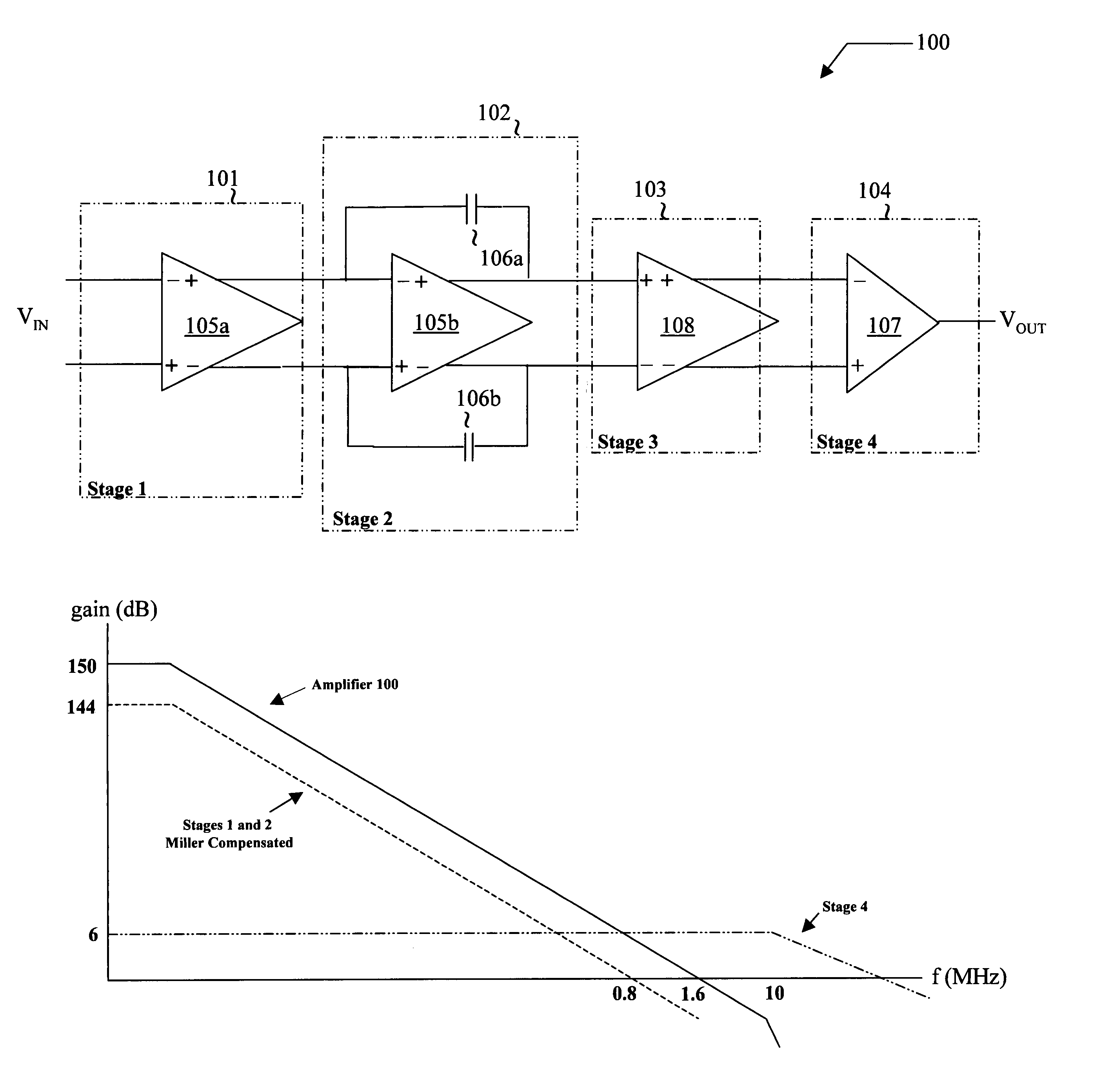
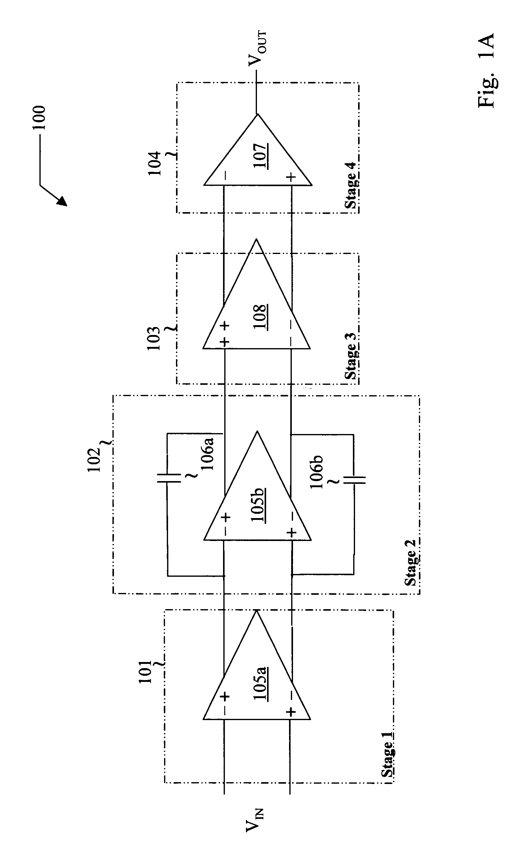
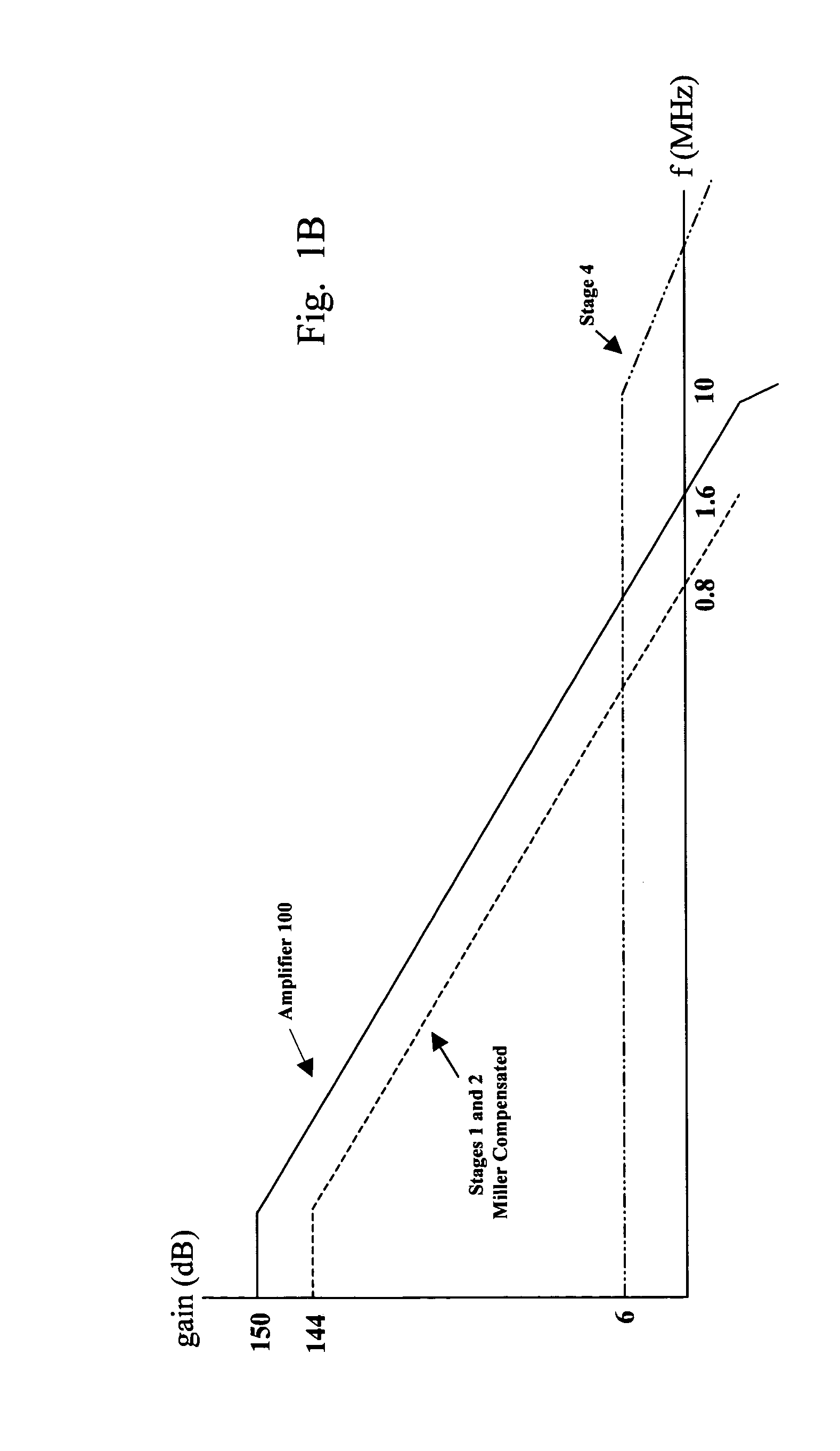
[0015]FIG. 1A is a high-level block diagram of an exemplary multiple-stage operational amplifier (opamp) 100 embodying the principles of the present invention. Opamp 100 includes two (2) gain stages 101 and 102, an intermediate stage 103, and an output driver stage 104, although in alternate embodiments the number of gain stages may vary.

[0016]First gain stage 101, which includes an amplifier 105a, controls the input characteristics of opamp 100. In one embodiment, amplifier 105a of first gain stage 101 includes parallel NMOS and PMOS input transistors such that the input signal VIN can swing from rail to rail (i.e. 0 v to VDD). In the illustrated embodiment first gain stage 101 provides a low frequency gain of greater than 80 dB. Second gain stage 102 includes an amplifier ...


PUM


Abstract

A multiple-stage operational amplifier including a gain stage for amplifying an input signal and implementing a dominant pole producing a frequency response having a gain roll-off with frequency and a unity gain frequency. An intermediate stage is coupled to an output of the gain stage and has a high input impedance and a low output impedance. A high gain amplifier configured as a low gain output stage using resistive feedback and coupled to an output of the intermediate stage drives an output of the operational amplifier and implements a dominant pole at a frequency substantially higher than the unity gain frequency implemented by the dominant pole implemented the gain stage.

Description

FIELD OF INVENTION[0001]The present invention relates in general to linear circuit techniques, and in particular to multiple-stage operational amplifiers and methods and systems utilizing the same.BACKGROUND OF INVENTION[0002]Multiple-stage operational amplifiers (opamps) typically include a cascade of one or more gain stages and an output driver stage for driving an output load. The output stage is, for example, a Class AB amplifier that provides high low-frequency gain. To achieve an overall high open loop gain (e.g. greater than 150 dB), a multiple-stage opamp normally requires three or more gain stages.[0003]The design of multiple-stage opamps with three or more gain stages presents significant design challenges. For example, to achieve unconditional stability, a relatively complex nested Miller frequency compensation scheme must often be used. In the nested Miller frequency compensation scheme, as each new gain stage is added to the system, an additional nested Miller capacitor...

Claims


Application Information

Patent Timeline
IPC IPC(8): H03F3/04
CPCH03F1/08H03F3/45H03F3/45937H03F3/68H03F2203/45512
Inventor KEJARIWAL, MURARIVEMULAPALLI, GOWTHAMMELANSON, JOHN LAURANCE
Owner CIRRUS LOGIC INC
Why Eureka
Try Eureka