Method for repairing an apertured gas turbine component

a gas turbine and component technology, applied in the direction of machines/engines, superimposed coating processes, manufacturing tools, etc., can solve the problems of thermal barrier coating, metallic bond coating and ceramic top coating, degrading in certain surface areas, reducing the service life of the component, so as to increase the number of times a component can be repaired, the effect of less expensive and time-consuming

Inactive Publication Date: 2007-04-17
RTX CORP
View PDF27 Cites 64 Cited by
  • Summary
  • Abstract
  • Description
  • Claims
  • Application Information

AI Technical Summary

Benefits of technology

[0018]The present invention is directed towards a repair for gas turbine components coated with a thermal barrier coating that increases the number of times a component can be repaired and is less expensive and time consuming prior art repair method.

Problems solved by technology

During normal engine operation and after time, the thermal barrier coating, including the metallic bond coat and the ceramic top coat, will degrade in certain surface areas most subjected to strenuous operating conditions.
Although high quality diffusion holes provide superior performance, they are both costly and difficult to form.
Removal of the bond coat after removal of the ceramic top coat may be required due to surface degradation of the bond coat especially in those surface areas most subject to strenuous operating conditions.
The filing process is both labor intensive and costly and will necessitate the remanufacture of the filled cooling holes, including the diffusion holes.
During this repair process, if the blade should have any cooling holes, these cooling holes may be subject to being partially or completely filled with the non-original coating material.
This phenomenon is known as “coatdown” and can restrict the flow capacity of the affected holes.
The effects of coatdown can diminish the cooling effectiveness of the film cooling thereby reducing the component's useful operating life.
Any cooling holes that are subject to coatdown are typically unacceptable for return to service and will require reworking to remove the excess nonoriginal coating before the blade can be put back into service.
However, the erosive treatment can be inaccurate and nonrepeatable and is tedious and time consuming since a typical turbine airfoil has many rows of cooling holes.
It is difficult, however, to produce shaped holes (diffusion holes) with this technique.
This is a significant repair limitation because the geometry of the holes partially determines the effectiveness of cooling.
Although the above EDM method is successful, limitations exist.
EDM is a time intensive and relatively expensive process compared to other processes such as laser drilling.
Also, the electrodes are fragile and are not reusable.
The use of EDM to remanufacture the diffusion cooling holes in a typical vane is labor intensive and expensive.

Method used


Image

  • Method for repairing an apertured gas turbine component
  • Method for repairing an apertured gas turbine component
  • Method for repairing an apertured gas turbine component

Examples


Embodiment Construction

[0031]The method of the present invention may be used to repair any gas turbine components or articles such as blades or vanes that are coated, in particular with a thermal barrier coating system. A thermal barrier coating system comprises a metallic bond coat and a top coat. Typically, engine run high pressure turbine airfoils, such as vanes, are candidates for the repair of the present invention.

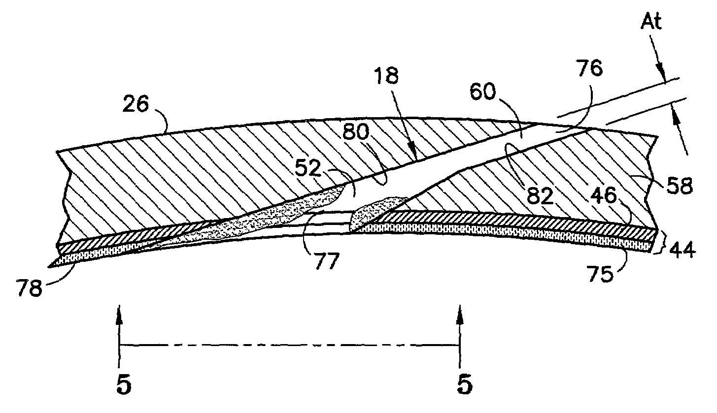
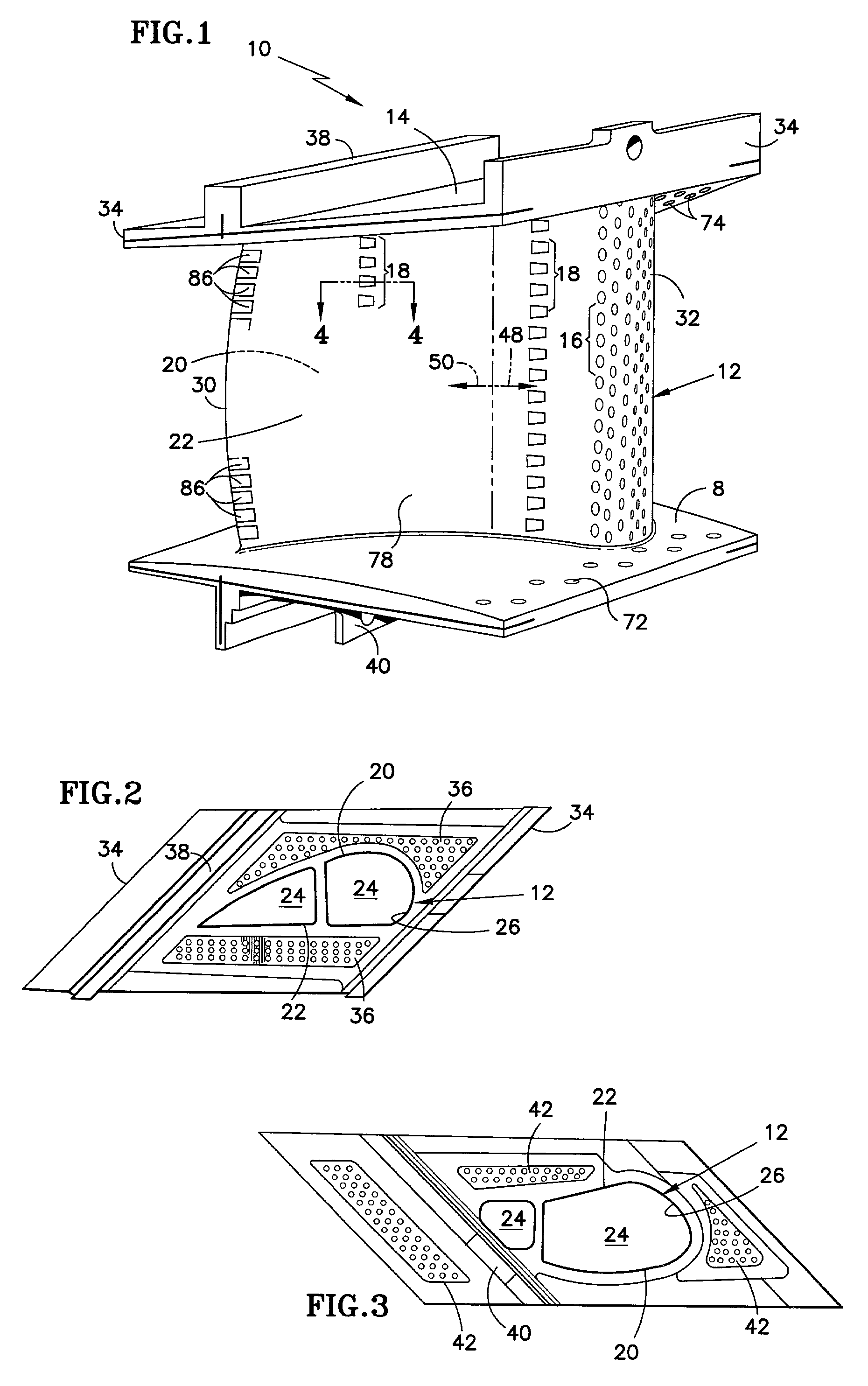
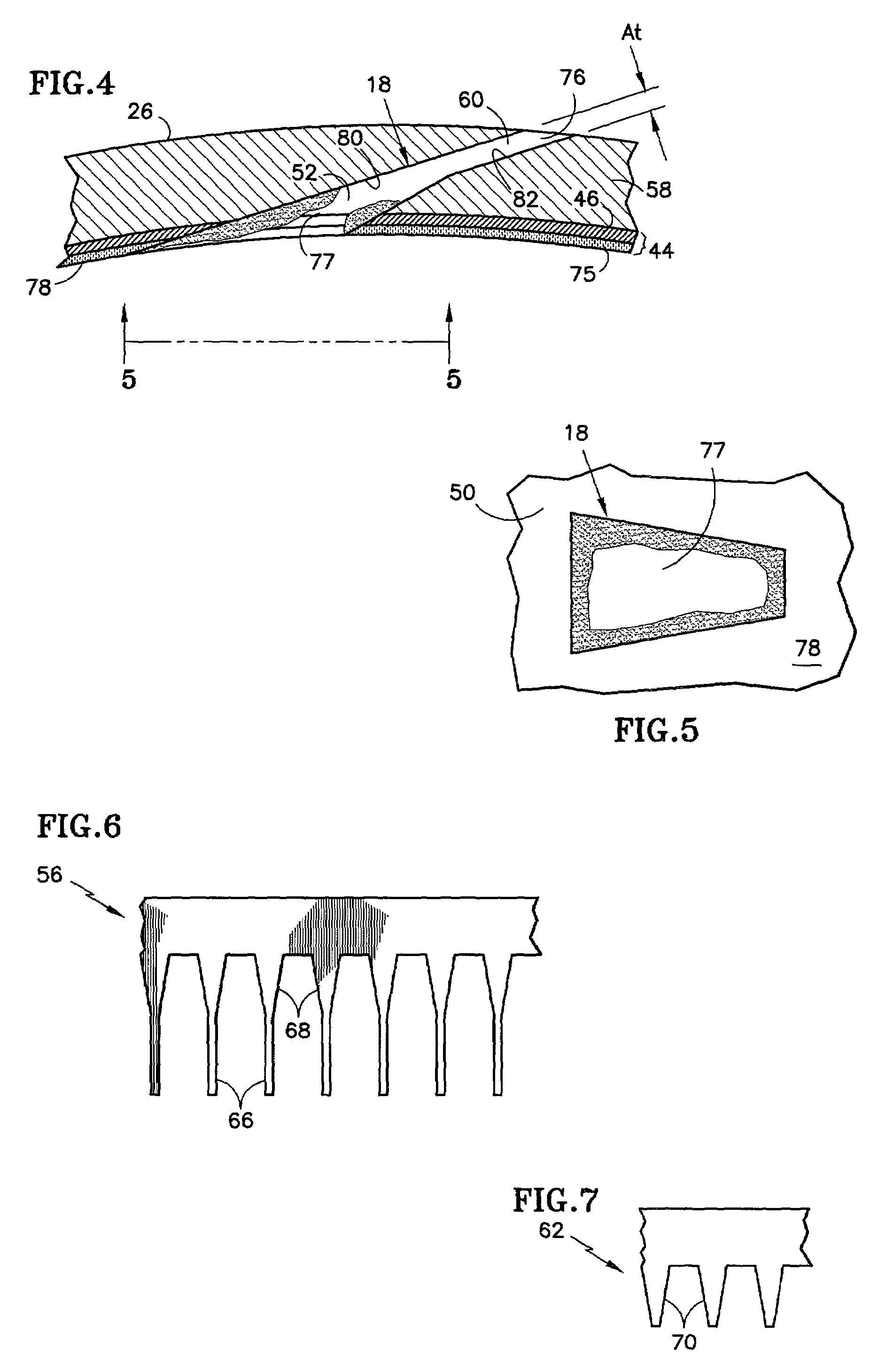
[0032]Referring to FIG. 1, a high pressure turbine vane (article) 10 is shown. Referring also to FIGS. 2 and 3, a top view and a bottom view are respectively shown for the vane 10 of FIG. 1. The vane 10 comprises an airfoil section (airfoil) 12 having at least one internal cavity 24 (FIG. 2), the internal cavity 24 having an internal surface 26 (FIG. 2). The airfoil section 12 has a convex surface 20 and a concave surface 22. The convex and concave surfaces 20, 22, respectively, are bounded by a trailing edge 30 and a leading edge 32 and together form an exterior surface 78 of the airfoil....


PUM

PropertyMeasurementUnit
temperatureaaaaaaaaaa
depthaaaaaaaaaa
widthaaaaaaaaaa

Abstract

A method for repairing defects in a gas turbine component that comprises a substrate and an existing coating on the substrate. The article includes cooling holes having a predetermined air flow requirement and an outer shaped portion and an inner metering portion. The method comprises removing the existing coating and recoating the surface of the article with a nonoriginal coating. After the nonoriginal coating is applied onto the component, the cooling holes that meet a predetermined inspection criteria are reworked to remove the excess nonoriginal coating deposited in the outer shaped portion of the cooling holes. The reworking is done by receiving an electrode, having only a shaped portion with a preselected shape, in the outer shaped portion of the cooling holes thus restoring the cooling holes to the predetermined air flow requirement.

Description

TECHNICAL FIELD[0001]The present invention is directed to repairs of a coated gas turbine component, and more particularly, to repairs of defects in an air-cooled gas turbine vane having diffusion cooling holes where the vane is coated with a thermal barrier coating (TBC) system.BACKGROUND OF THE INVENTION[0002]Over the years, gas turbine engine manufacturers have increased the temperature and pressure at which gas turbine engines operate to meet demands for more powerful and efficient engines. The increased temperature and pressure levels have imposed rigorous operating conditions on certain engine components, particularly turbine vanes and blades immediately downstream of a combustor. In modern engines, turbine vanes and blades may be exposed to temperatures above the melting point of the alloy from which they are made.[0003]While manufacturers have been designing gas turbine engines that operate under very demanding conditions, they have been striving to improve gas turbine engin...

Claims


Application Information

Patent Timeline
Patent Type & Authority Patents(United States)
IPC IPC(8): B23P6/00B23P19/04B23H9/10F01D5/18B23H9/14B23K31/00C23C4/02C23C4/18C23C28/04F01D5/00F01D5/28F02C7/00
CPCB23H9/10B23P6/002C23C4/02C23C4/18C23C28/32C23C28/3455F01D5/005C23C28/345B23H9/14Y10T29/49721B23P2700/06F05D2250/232F05D2260/202F05D2230/12F05D2230/90Y10T29/49726Y10T29/4973Y10T29/49746Y10T29/49339Y10T29/49341Y10T29/49318
Inventor DUCOTEY, JR., HOWARD S.ZUBER, ROBERT J.DRAGHI, PETER J.
Owner RTX CORP
Why Eureka
Try Eureka