Vascular filter with improved strength and flexibility

a vascular filter and improved technology, applied in the field of medical devices, can solve the problems of easy tear of membranes, difficulty in using tortuous arteries, and filter holes not having a well-defined and constant size, and achieve the effect of improving strength and flexibility

Inactive Publication Date: 2007-05-08
DON MICHAEL INT
View PDF24 Cites 91 Cited by
  • Summary
  • Abstract
  • Description
  • Claims
  • Application Information

AI Technical Summary

Benefits of technology

[0028]The present invention provides novel medical devices, such as vascular filters, with improved strength and flexibility and methods for their manufacture. These filters have a proximal frame section and a distal section, which can be collapsed into a small diameter delivery catheter and expanded upon release from this catheter. The proximal section is made as a frame of a relatively rigid material compared to the material of the distal section, for example a metal, and the distal section is provided with a flexible thin membrane, with perfusion holes in filter devices, of a diameter that allows blood to pass, but prevents the passage of emboli. The distal filter membrane has a proximal entrance mouth, which has almost the same size as the body lumen of a patient when the filter is deployed. The membrane is attached to the proximal section, which has the function to keep the mouth of the distal filter open and to prevent the passing of emboli between the body lumen wall and the edge of the filter mouth.

Problems solved by technology

Normally this would create the risk that the membrane could tear easily, which could cause problems because emboli and pieces of the membrane would then be carried downstream from the filter site.
These filters do not have a well-defined and constant size of the holes where the blood flows through, because of the relative movement of the filaments in the mesh.
This is a disadvantage, because the size of emboli can be very critical, e.g. in procedures in the carotid arteries.
First of all, the closed basket construction makes this filter frame rather rigid and therefore it is difficult to be used in tortuous arteries.
At a curved part of an artery, it may even not fit well against the artery wall and will thus cause leakage along the outside of the filter.
Another disadvantage of such filters is there is a high risk of squeezing-out the caught debris upon removal, because the struts of the framework force the debris back in the proximal direction, while the volume of the basket frame decreases when the filter is collapsed.
Further the construction makes it very difficult to reduce the profile upon placement of the filter.
In the just described filter miniaturization would be difficult because at a given cross section there is too much material.
During angioplasty and stenting, the movements of the guide wire will create further forces that influence the position and shape of the filter, which may cause problems with the proper sealing against the artery wall.
If the filter is brought into a delivery sheath of small diameter, collapsing the frame and pulling the bag into the delivery sheath causes rather high forces on the connection sites of filter to frame and / or guide wire.
While the metal parts of the frame slide easily through such a delivery sheath, the membrane material may have the tendency to stick and in the worst case it may even detach from the frame and tear upon placement or during use, because of too much friction, unlimited expansion, crack propagation etc.
The procedures currently employed result in a fracturing or disintegration of the obstructing material and if the resulting particles, or debris, were permitted to flow downstream within the circulatory system, they would be likely to cause blockages in smaller arteries, or their microscopic branches termed the microcirculation, downstream of the treatment site.
The result can be new life-threatening conditions, including stroke.
While such techniques can effectively solve the problem stated above, they require that blood flow through the artery be obstructed, causing complete cessation or at least a substantial reduction in blood flow volume, during a time period which can be significant for organ survival for example, the time limit for the brain is measured in seconds and for the heart, in minutes.
Although filters have been used, they suffer from the limitation of either obstructing flow or allowing micro embolism due to fixed pore size.
Furthermore, the collected debris can reflux out of the filter when it is closed and lead to embolism.
This is an extra, time-consuming step in the procedure.

Method used


Image

  • Vascular filter with improved strength and flexibility
  • Vascular filter with improved strength and flexibility
  • Vascular filter with improved strength and flexibility

Examples


Embodiment Construction

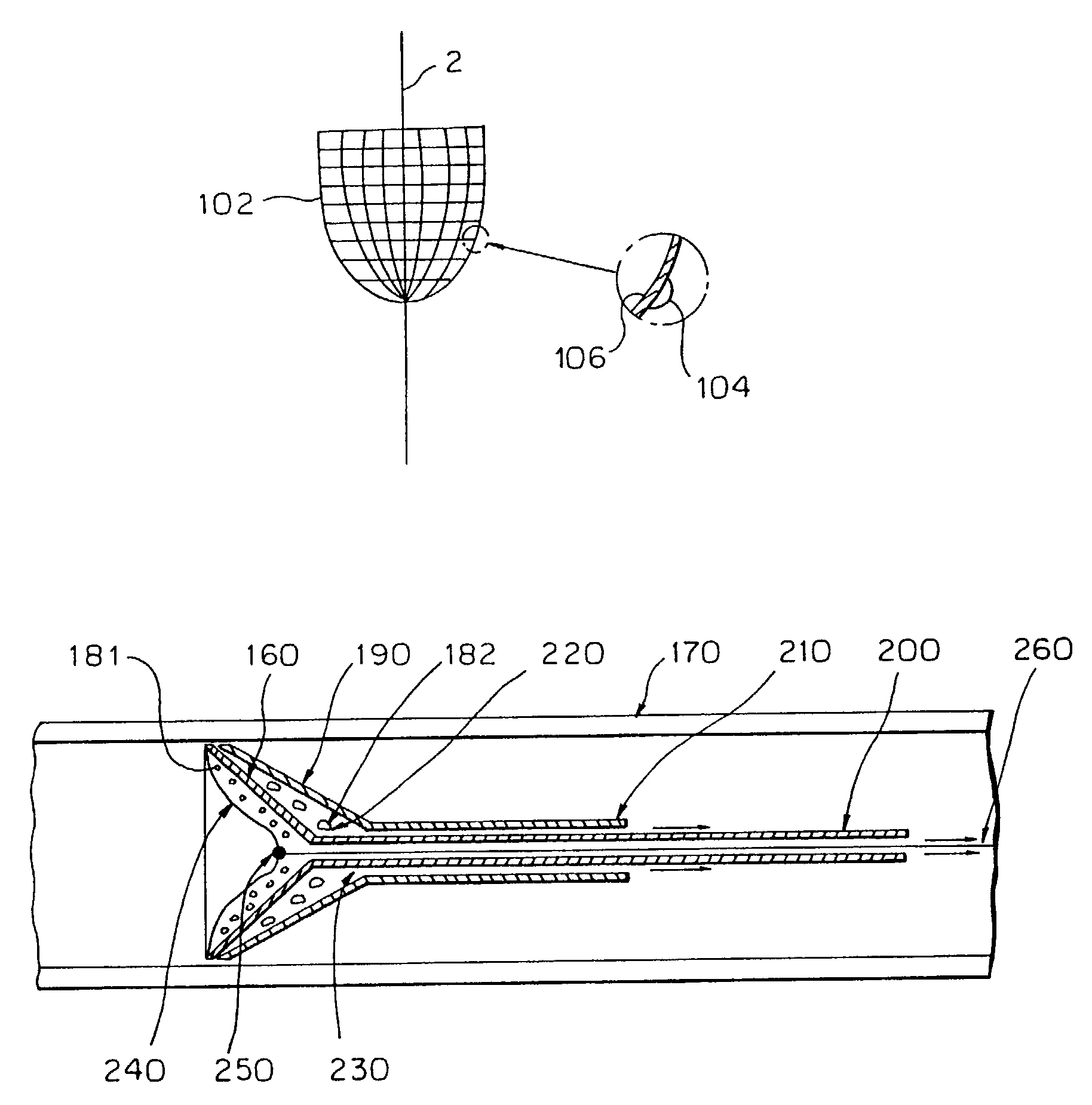
[0075]The invention provides a novel method and a system to confine and remove debris from a blood vessel, thereby preventing embolism in the vascular system.

[0076]A first step of one embodiment of a method according to the invention includes positioning a first particle filter in the blood vessel downstream of the treatment site.

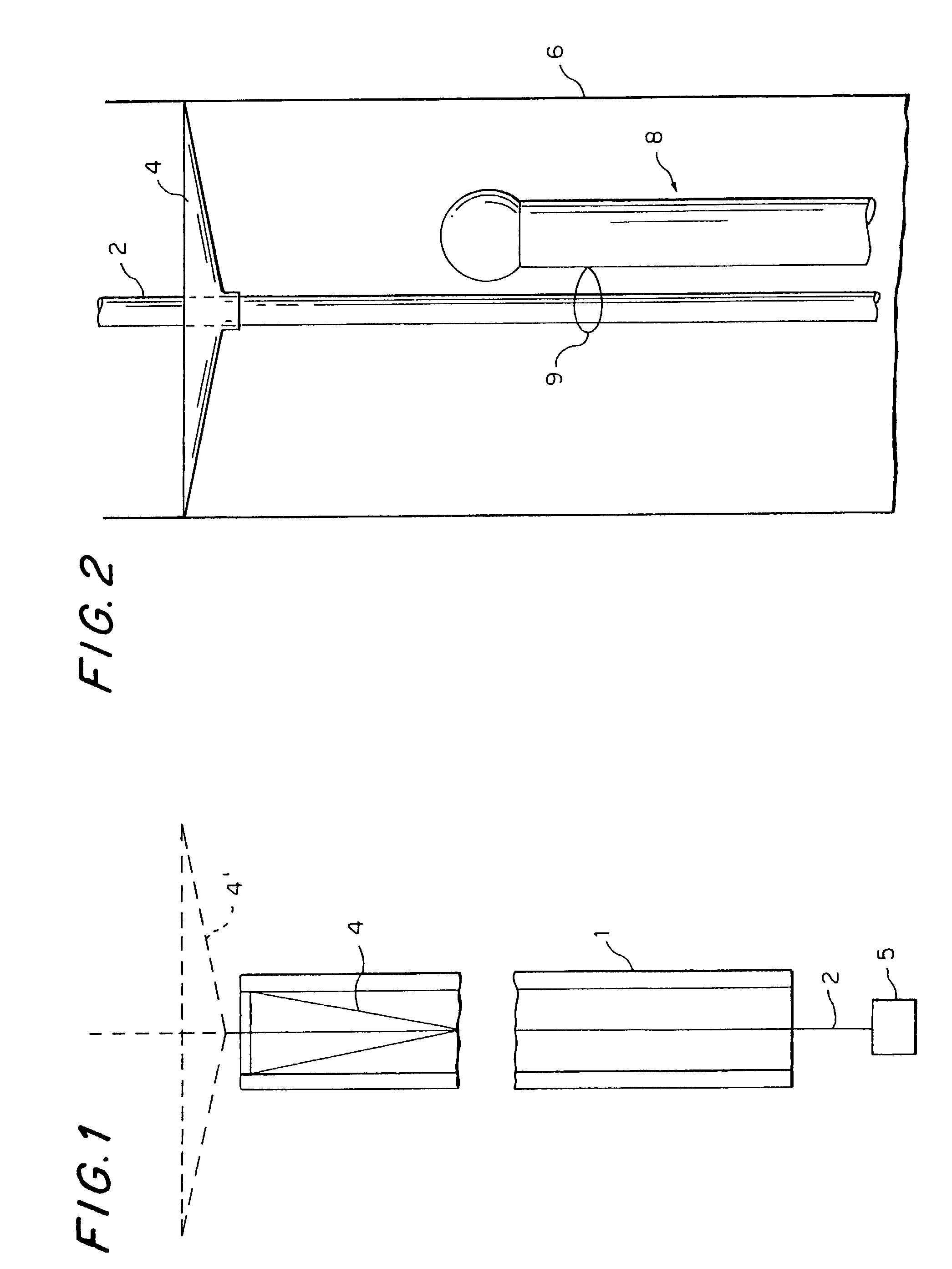
[0077]FIG. 1 is a cross-sectional elevational view of a first unit of a protective system according to the invention for carrying out the first step. This unit is composed of a sheath 1, a hollow guide wire 2 and a distal particle filter 4.

[0078]Filter 4 may have any shape, for example a conical shape, as shown, and is constructed to be radially expansible from a radially compressed state, shown in solid lines, to a radially expanded state, shown in broken lines at 4′. Preferably, at least one part of filter 4 is made of a resiliently deformable material that autonomously assumes the radially expanded state shown at 4′ when unconstrained. Filter 4 may be sh...


PUM

PropertyMeasurementUnit
particle sizeaaaaaaaaaa
diameteraaaaaaaaaa
diameteraaaaaaaaaa

Abstract

A medical device, such as a vascular filter, composed of: a reinforced membrane unit composed of: a thin filter membrane; and fibers of reinforcement material embedded in the membrane to strengthen the filter and securely attach the fibers to the membrane.
A method of fabricating the filter by the steps of: providing a mold that can be melted, dissolved, or deformed without damaging membrane material; covering the mold with an intermediate material that is easily separated from the membrane material; covering the intermediate material with the membrane material; placing the fibers in contact with the membrane material that covers the intermediate material; covering the fibers with additional membrane material to form the membrane with embedded fibers; removing the mold by melting, dissolving, or deforming the mold; and removing the intermediate material from the membrane.

Description

[0001]This is a continuation-in-part of allowed U.S. application Ser. No. 09 / 803,641, filed on Mar. 12, 2001, now U.S Pat. No. 6,485,502, the entire disclosure of which is incorporated herein by reference. This application also claims the benefit of the filing dates of the following U.S. Provisional Applications: No. 60 / 412,071, filed Sep. 19, 2002; No. 60 / 417,408, filed Oct. 9, 2002.BACKGROUND OF THE INVENTION[0002]This invention relates to medical devices, such as vascular filters to be used in a body lumen, such as a blood vessel, with improved strength and flexibility. A filter according to the invention includes a proximal frame section, a distal section and a flexible thin membrane with perfusion holes of a diameter that allows blood to pass, but prevents the movement of emboli downstream.[0003]Both sections can be collapsed into a small diameter delivery catheter and expanded upon release from this catheter. The membrane has a proximal entrance mouth, which can be expanded, o...

Claims


Application Information

Patent Timeline
Patent Type & Authority Patents(United States)
IPC IPC(8): A61M29/00A61F2/01
CPCA61F2/013A61F2002/018A61F2230/0006A61F2230/005A61F2230/0067A61F2230/008A61F2230/0093A61F2/012
Inventor DON MICHAEL, T. ANTHONYBESSELINK, PETER
Owner DON MICHAEL INT
Why Eureka
Try Eureka