Ultrasonic transmitter, ultrasonic transceiver and sonar apparatus

a transceiver and ultrasonic technology, applied in ultrasonic/sonic/infrasonic diagnostics, instruments, applications, etc., can solve the problems of inability to receive echoes from nearby targets, interference fringes or false images of sonar equipment on nearby ships, and inability to detect false targets, etc., to suppress the occurrence of undetectable transmitting frequency components.

Active Publication Date: 2007-05-08
FURUNO ELECTRIC CO LTD
View PDF9 Cites 58 Cited by
  • Summary
  • Abstract
  • Description
  • Claims
  • Application Information

AI Technical Summary

Benefits of technology

[0019]It is an object of the invention to provide a compact, low-loss ultrasonic transmitter which makes it possible to suppress the occurrence of undesired transmitting frequency components by controllably shaping driving pulse signals for driving transducer elements of a transducer into a desired waveform (envelope shape) and to instantly set up desired spatial weights to be assigned to ultrasonic waves emitted from the individual transducer elements through a pulse-duration modulation process. It is a further object of the invention to provide an ultrasonic transceiver and a sonar apparatus including such an ultrasonic transmitter.

Problems solved by technology

Since echo signals received by the sonar apparatus on the nearby ship are affected by the undesired frequency components radiated from the own ship's scanning sonar, the sonar apparatus on the nearby ship would present interference fringes or false images.
However, frequency response (transfer function) of this kind of matching circuit often contains components (spurious) responsive to frequencies other than a center frequency.
When such a ringing phenomenon occurs, a single underwater object (or target) will return multiple target echoes, causing the sonar to detect false targets.
In addition, the oscillatory transient caused by the ringing phenomenon following the rectangular-shaped driving pulse signal overlaps echo signals received immediately after transmission of a rectangular-shaped ultrasonic pulse signal, making it impossible to receive echoes from nearby targets, such as bottom echoes in shallow areas.
It is however impossible to control the envelope shape of the driving pulse signal such that its amplitude varies gradually by the aforementioned conventional switching-type circuit configuration which produces the driving pulse signal from rectangular pulse signals of a fixed waveform.
Thus, the conventional switching-type circuit configuration is associated with a problem that it can not produce a driving pulse signal of a desired waveform.
Again, it is impossible to vary the amplitude of the ultrasonic waves with the conventional switching-type circuit configuration which produces the driving pulse signal from rectangular pulse signals of a fixed waveform, unless the amplitude of a power supply voltage waveform is varied.
Although a variable voltage power supply circuit can produce a power supply voltage waveform of a varying amplitude, the variable voltage power supply circuit uses a capacitor of a large capacity which requires a long time for charging and discharging.
However, it is necessary to provide D / A converters for the individual transducer elements in the linear-type circuit configuration and this results in large power consumption.
Also, the linear-type circuit configuration necessitates a large number of components, resulting in an increase in overall equipment size.
Furthermore, since the transistors Tr1, Tr2 are operated in their non-saturation area, there occurs a large loss, making it impossible to achieve high efficiency.

Method used


Image

  • Ultrasonic transmitter, ultrasonic transceiver and sonar apparatus
  • Ultrasonic transmitter, ultrasonic transceiver and sonar apparatus
  • Ultrasonic transmitter, ultrasonic transceiver and sonar apparatus

Examples


Embodiment Construction

[0058]A scanning sonar including an ultrasonic transceiver according to a specific embodiment of the invention is now described with reference to the appended drawings.

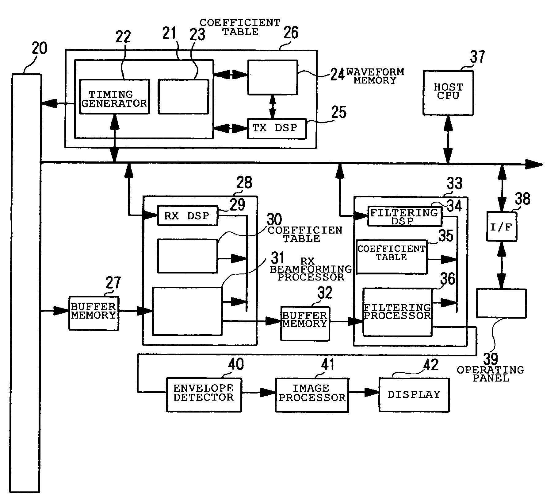
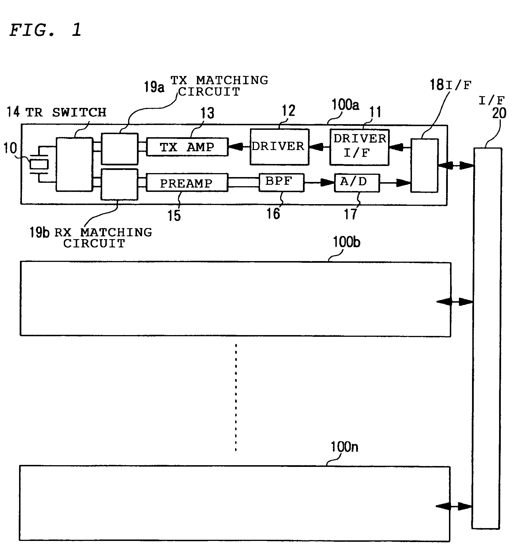
[0059]FIG. 1 is a block diagram generally showing the configuration of transmit-receive channels 100 of the scanning sonar.

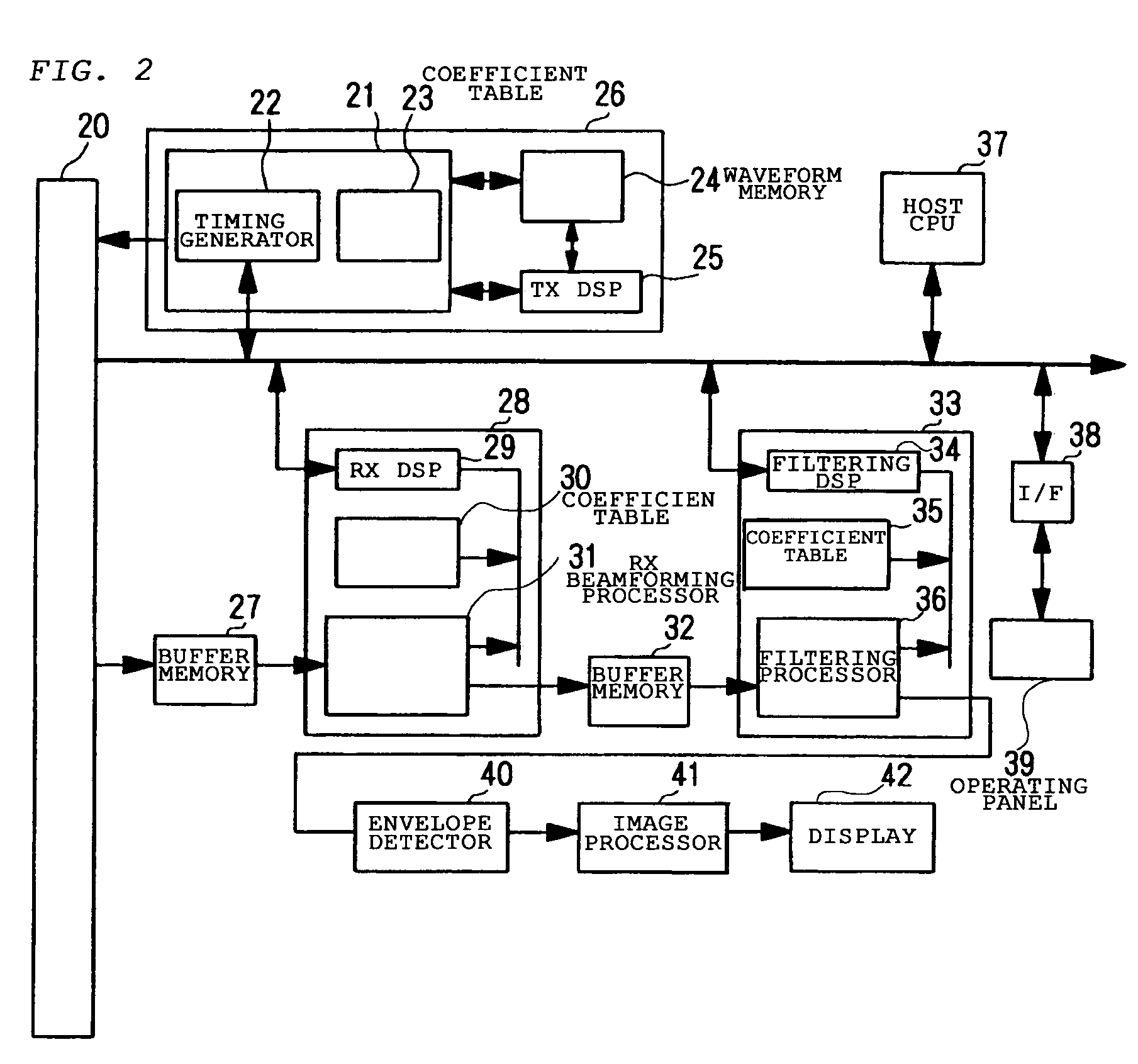
[0060]Referring to FIG. 1, each transmit-receive channel 100 includes a driver interface 11 which generates a pulse drive signal for producing a reference signal, which is converted into a carrier drive signal through a pulse-duration modulation (PDM) process, based on a clock signal, a control signal and driving code data supplied from a later-described programmable transmitting beamformer 26. The driver interface 11 is essentially a programmable logic device (PLD). A driver circuit 12 produces the reference signal from the pulse drive signal. A transmitting amplifier circuit 13 amplifies the reference signal and a transmit-receive switching circuit 14 produces the carrier drive signal (of which ...


PUM


Abstract

An ultrasonic transmitter generates a reference signal based on a clock signal of a specific frequency and a control signal made up of binary values 0 and 1 for controlling how the level (High or Low) of a carrier drive signal should change, and generates an analog signal constituting the carrier drive signal by pulse-duration-modulating the reference signal. Produced from the carrier drive signal, a driving pulse signal is shaped into a curved waveform having a gradually rising leading edge and a gradually falling trailing edge as the amplitude of the carrier drive signal is gradually increased and decreased based on the control signal.

Description

[0001]This Nonprovisional application claims priority under 35 U.S.C. § 119(a) on Patent Application No. 2002-343913 filed in JAPAN on Nov. 27, 2002, the entire contents of which are hereby incorporated by reference.BACKGROUND OF THE INVENTION[0002]1. Field of the Invention[0003]The present invention relates to an ultrasonic transmitter for radiating ultrasonic waves into a body of water, for instance, an ultrasonic transceiver for radiating ultrasonic waves and receiving echoes of the radiated ultrasonic waves, and a sonar apparatus including an ultrasonic transceiver for detecting objects using ultrasonic waves.[0004]2. Description of the Related Art[0005]Today, sonar apparatuses, such as scanning sonars, are widely used for detecting underwater objects. A scanning sonar for detecting underwater objects all around has a generally cylindrical transducer. The scanning sonar forms an ultrasonic transmitting beam oriented in all directions around the transducer by activating transduce...

Claims


Application Information

Patent Timeline
Patent Type & Authority Patents(United States)
IPC IPC(8): H04B1/02A61B8/00H04B1/38G01S7/524G01S7/52G01S7/523G01S15/10G10K11/34
CPCG01S7/52003G01S15/101G10K11/341G01S15/10
Inventor NISHIMORI, YASUSHIHANDA, MINORUOZASA, SHIROHNISHIDA, MASARUMATSUMOTO, HIROMUNE
Owner FURUNO ELECTRIC CO LTD
Why Eureka
Try Eureka