Integrated inertial stellar attitude sensor

a technology of inertial stellar attitude and sensor, which is applied in the direction of instruments, process and machine control, etc., can solve the problems of blurred star position and brightness, star camera field of view (fov) may be changing too fast, and the star tracker camera may not be able to focus on the fov, etc., to achieve low power and volume requirements, high accuracy, and robust

Active Publication Date: 2007-05-08
CHARLES STARK DRAPER LABORATORY
View PDF10 Cites 30 Cited by
  • Summary
  • Abstract
  • Description
  • Claims
  • Application Information

AI Technical Summary

Benefits of technology

[0011]It is a further object of this invention to provide an attitude sensor having high accuracy with low power and volume requirements.
[0012]It is a further object of this invention to provide a more robust, less expensive attitude sensor.

Problems solved by technology

If the spacecraft is undergoing high slew rates, i.e. is moving too fast or tumbling, the star camera field of view (FOV) may be changing too fast, and the star tracker camera may not be able to focus on the FOV.
The position of stars and the brightness of stars is therefore blurred and cannot be resolved by the star camera sufficiently to be properly compared to a star catalog of known star patterns.
Also, if the star camera system has no prior knowledge of the attitude of the aerospace vehicle, it must rely on use of a “lost-in-space” algorithm, where the star identification process is computationally more intensive because of the lack of base information regarding prior aerospace vehicle attitude.
This results in poor resolution and consequent inability to properly match the star pattern in the star camera field-of-view with star patterns in the star catalog.
Inherent errors associated with gyroscopes as known by those skilled in the art include gyroscope “drift”, bias and scale factor errors, which affect the accuracy of the gyroscope output.
Their size, weight, control electronics, and power requirements of CCDs prohibit their use in small satellite applications.
CCDs are also susceptible to radiation damage and conventional gyroscopes suffer from the further disadvantages of size and weight, sensitivity to vibrations, and susceptibility to radiation.
The combination of CCD star camera systems and conventional gyroscope systems decreases the effects of image blurring and lack of resolution when the vehicle's attitude rate exceeds the camera's optical tracking limit.
This is a cumbersome, highly power and computationally intensive and expensive process that is prone to error.
Also, the star camera system and the gyroscope system are separate from each other structurally, adding weight to the overall aerospace vehicle attitude determination system.
Integrating each system's outputs in software creates unnecessary design risk because the engineers performing the integration are not the same engineers who designed and best understand each system's hardware.
Furthermore, third party integration and lack of insight into the design of each system leads to less than optimum performance.
Also, this “external” fusion of gyroscopes and star trackers requires large mass and high power, which prohibits applications in smaller vehicles such as nanosatellites.
Spacecraft of less than ten kilograms cannot use traditional gyroscopes and star tracker cameras at all.
Moreover, the cost of the separate systems, together with the cost of integrating the two systems externally, is quite expensive.

Method used


Image

  • Integrated inertial stellar attitude sensor
  • Integrated inertial stellar attitude sensor
  • Integrated inertial stellar attitude sensor

Examples


Embodiment Construction

[0066]Aside from the preferred embodiment or embodiments disclosed below, this invention is capable of other embodiments and of being practiced or being carried out in various ways. Thus, it is to be understood that the invention is not limited in its application to the details of construction and the arrangements of components set forth in the following description or illustrated in the drawings.

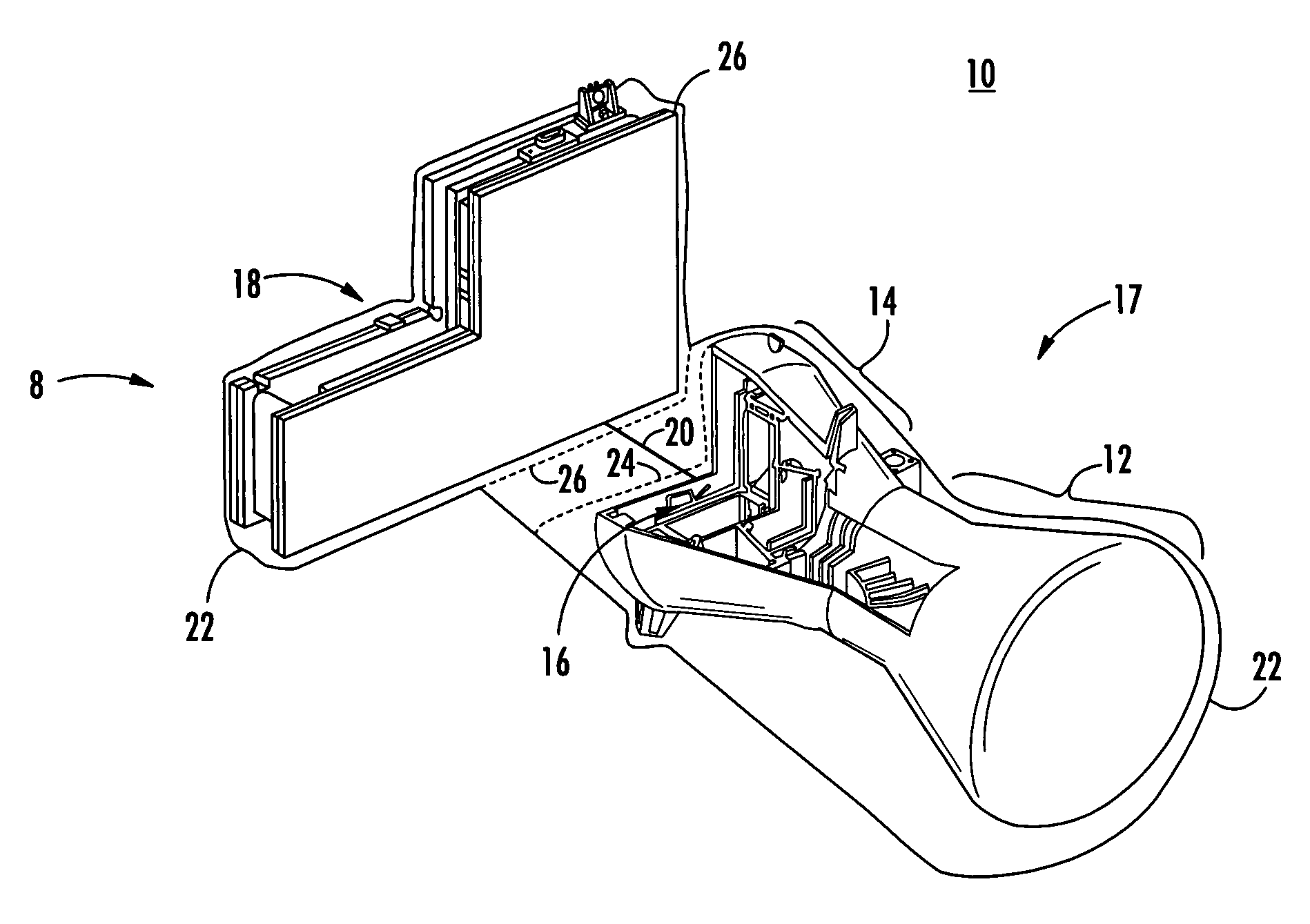
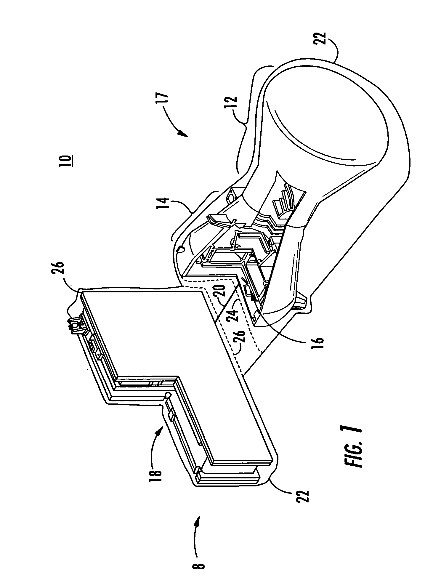
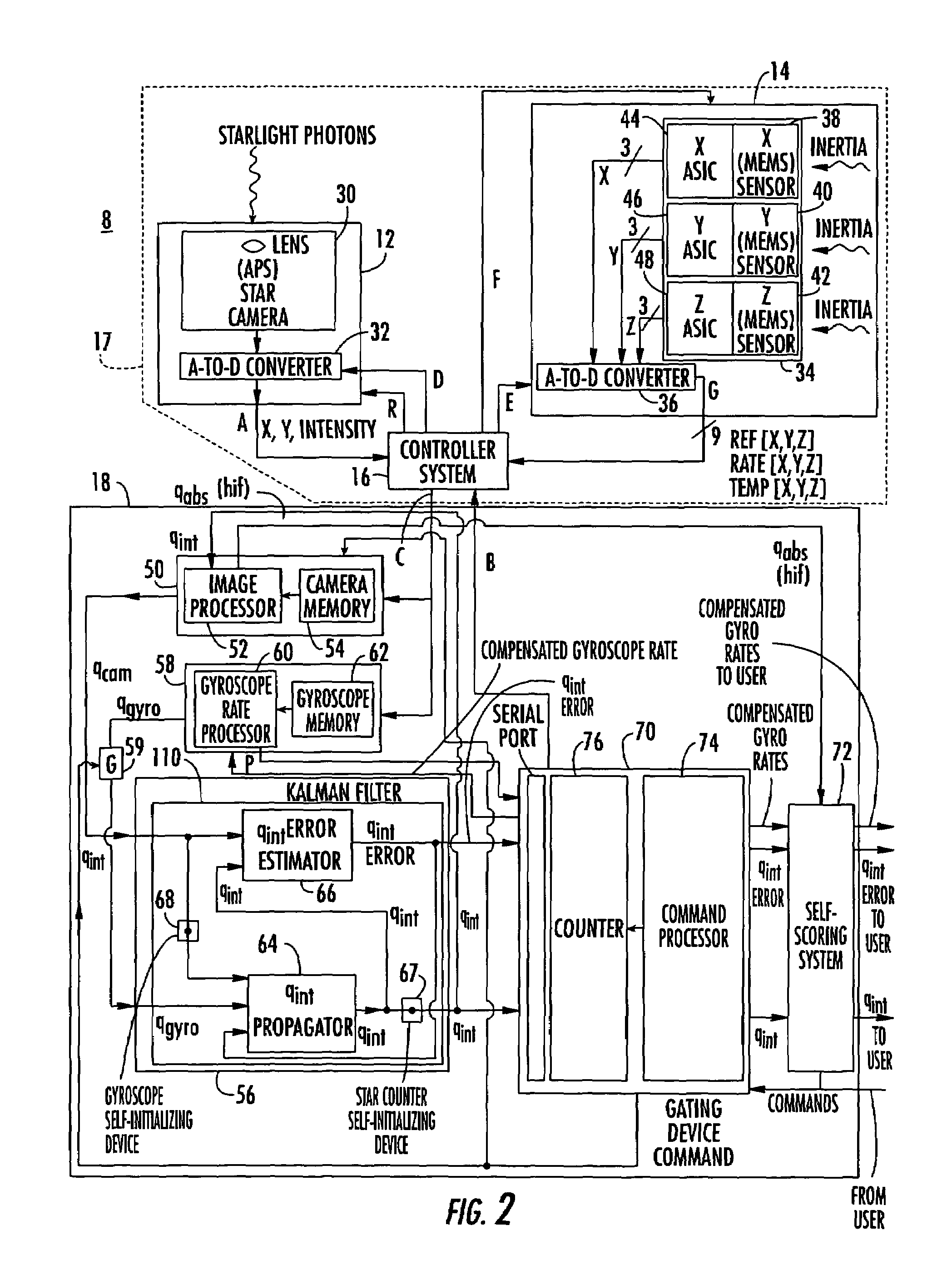
[0067]An integrated inertial stellar attitude sensor 8 for an aerospace vehicle 10 of one embodiment of this invention includes star camera system 12, gyroscope system 14, controller system 16 and data processing assembly or flight computer 18. Collectively, star camera system 12, gyroscope system 14 and controller system 16 may be referred to as camera / gyroscope assembly 17, which may be connected to flight computer 18 by connector 20. Connector 20 may be any appropriate connector known in the art including cable connections providing a serial link. Housing 22 may be disposed about integra...


PUM


Abstract

An integrated inertial stellar attitude sensor for an aerospace vehicle includes a star camera system, a gyroscope system, a controller system for synchronously integrating an output of said star camera system and an output of said gyroscope system into a stream of data, and a flight computer responsive to said stream of data for determining from the star camera system output and the gyroscope system output the attitude of the aerospace vehicle.

Description

RELATED APPLICATIONS[0001]This application claims priority of and is related to U.S. Provisional Patent Application Ser. No. 60 / 396,494 filed Jul. 16, 2002 entitled INERTIAL STELLAR COMPASS, which is fully incorporated herein by reference.GOVERNMENT RIGHTS[0002]This invention was made with U.S. Government support under Contract No. JPL Contract 1226271 awarded by the Jet Propulsion Laboratory (JPL) in support of NASA's New Millennium Program. The Government may have certain rights in the subject invention.FIELD OF THE INVENTION[0003]This invention relates to an integrated inertial stellar attitude sensor for an aerospace vehicle in which a star camera system, a gyroscope system and the outputs therefrom are integrated into a low mass, low power package to obtain accurate celestial attitude knowledge over a wide variety of operating conditions.BACKGROUND OF THE INVENTION[0004]Conventional systems for attitude determination of aerospace vehicles include star trackers and gyroscopes. U...

Claims


Application Information

Patent Timeline
Patent Type & Authority Patents(United States)
IPC IPC(8): G01C21/00B64G1/28B64G1/36G01C21/02G01C21/16
CPCB64G1/288B64G1/361B64G1/363G01C21/025G01C21/165B64G1/369
Inventor BRADY, TYE M.KOUREPENIS, ANTHONY S.WYMAN, JR., WILLIAM F.
Owner CHARLES STARK DRAPER LABORATORY
Why Eureka
Try Eureka