Apparatus and method of fabricating a compensating element for wavefront correction using spatially localized curing of resin mixtures

a technology of compensating elements and resin mixtures, applied in the field of optical elements, can solve the problems of inability to correct imperfections, expensive and time-consuming, and limited optical systems including the human ey

Inactive Publication Date: 2007-05-15
ESSILOR INT CIE GEN DOPTIQUE +1
View PDF67 Cites 45 Cited by
  • Summary
  • Abstract
  • Description
  • Claims
  • Application Information

AI Technical Summary

Benefits of technology

[0011]The optical element of one embodiment of the present invention includes a cavity. The cavity can be formed by a pair of transparent windows, or plates with a retaining ring, or spacer between the plates. The cavity is filled with one or more monomers, or pre-polymers, monomer mixtures and polymerization initiators (referred to generally herein as a resin mixture). This resin mixture exhibits an index of refraction change as it polymerizes, and the change is controlled by the extent of its polymerization, or curing. The curing of the resin mixture may be initiated by exposure to light, such as ultraviolet light. The exposure to light may be controlled spatially across and through the resin mixture to create a predetermined three-dimensional wavefront retardation profile. One application of such a wavefront retardation plate is to cancel the aberrations in an optical system, such that when an ideal plane wave passes through the wavefront retardation plate, a predetermined change of the wavefront profile can be affected by the wave plate, and when the wavefront subsequently passes through the optical system, aberrations introduced by the system (except for the intended focusing of the system) are cancelled. Alternatively, if the goal of the optical system is to establish a cylindrical lens, all aberration terms are cancelled, except for the desired astigmatism terms. Embodiments of the present invention have the ability to produce any retardation, including any one or any combination of the aberrations as describable by the Zernike polynomials.
[0012]The present invention is also applicable to the manufacturing of all conventional and specialized optical elements, including aspheric and other refractive surfaces, refractive elements (e.g., lenses), reflective elements (e.g., mirrors and beam splitters), and / or diffractive elements such as gratings, and Fresnel optics.

Problems solved by technology

While aspheric optics can be produced, to do so is costly and time consuming.
However, in reality optical systems including the human eye rarely are limited to what is conventionally assumed for purposes of providing corrective optics that have only spherical surfaces.
These imperfections unfortunately cannot be corrected by conventional glasses or contact lenses, leaving patients with less than optimum vision even after the best available corrective lenses have been prescribed.
Indeed, corrections to an optical system to minimize one type of aberration may result in the increase in one of the other aberrations.
As but one example, decreasing coma can result in increasing spherical aberrations.
This process can be iterative and time consuming, requiring, as it does, assembly, alignment, and performance evaluation to identify aberrations, followed by disassembly, polishing or grinding to correct the aberrations, and then reassembling and retest.

Method used


Image

  • Apparatus and method of fabricating a compensating element for wavefront correction using spatially localized curing of resin mixtures
  • Apparatus and method of fabricating a compensating element for wavefront correction using spatially localized curing of resin mixtures
  • Apparatus and method of fabricating a compensating element for wavefront correction using spatially localized curing of resin mixtures

Examples


Embodiment Construction

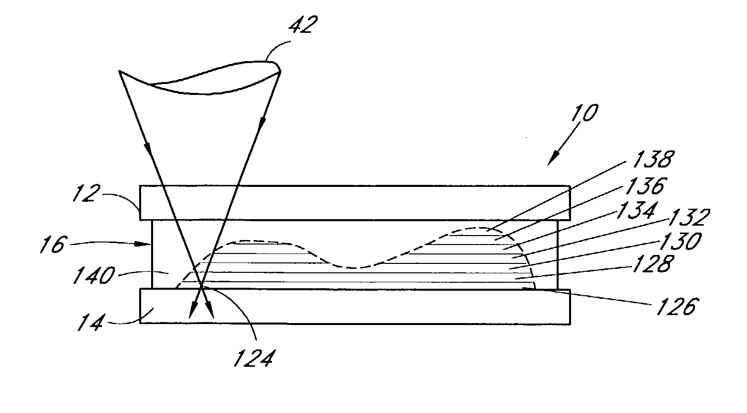
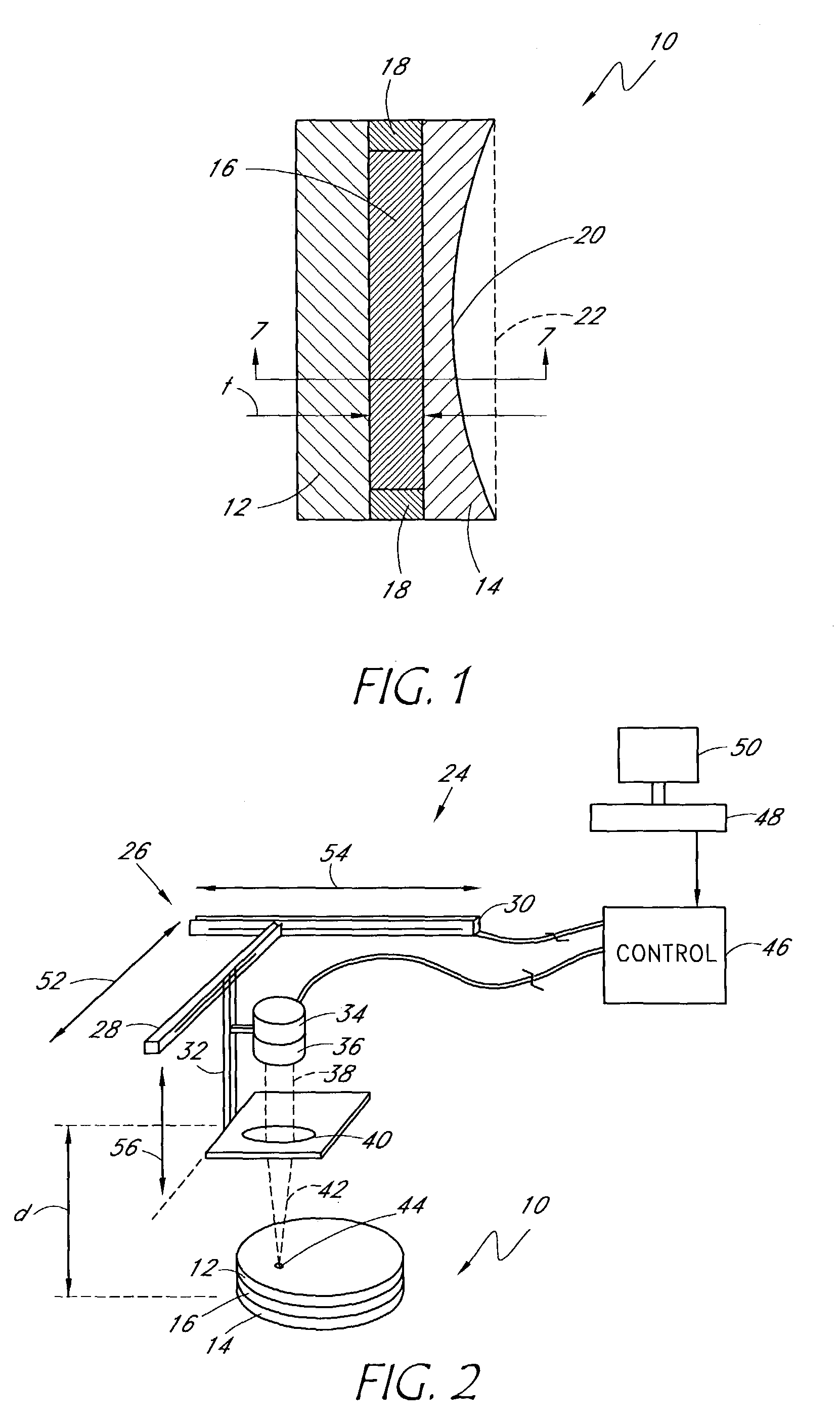
[0030]Referring initially to FIG. 1, a correcting element of the present invention is shown, generally designated 10. As shown, the correcting element 10 includes a first rigid or flexible transparent plate 12, a second rigid or flexible transparent plate 14, and a layer of resin mixture 16 sandwiched therebetween. If desired, a barrier 18 can be used to contain the resin mixture 16 between the plates 12, 14 prior to, and following, the below-described curing of the resin mixture.

[0031]The term “resin mixture,” as used herein, is intended to include light-curable resins comprised of one or more monomers, pre-polymers, polymers and polymerization initiators. The refractive index of the resin changes as the resin is cured, and it can be made to vary between locations within the resin layer depending on the spatial extent of curing of the resin mixture, as more fully disclosed below. The extent of curing is determined by the percentage of cross-linking between the monomers within the r...


PUM

PropertyMeasurementUnit
wavelengthsaaaaaaaaaa
cone angleaaaaaaaaaa
lengthaaaaaaaaaa

Abstract

An optical wavefront correction plate incorporates a unique, three-dimensional spatial retardation distribution utilizing the index of refraction change of resin mixture in its cured state. The optical wave plate comprises a pair of transparent plates, containing a layer of a monomers and polymerization initiators, such as resin mixture. This resin mixture exhibits a variable index of refraction as a function of the extent of its curing. Curing of the resin mixture may be made by exposure to light, such as ultraviolet light, and may be varied across and through the surface of the resin mixture to create a particular and unique three-dimensional wavefront retardation profile. The optical wave plate provides improved performance in large area mirrors, lenses, telescopes, microscopes, and ophthalmic diagnostic systems.

Description

RELATED APPLICATIONS[0001]A patent disclosure document of this application was filed and stamped by the U.S. Patent and Trademark Office on Dec. 27, 2000, Document No. 484302.BACKGROUND OF THE INVENTION[0002]1. Field of the Invention[0003]The present invention relates generally to producing optical elements for use in optical systems.[0004]2. Description of the Related Art[0005]In many optical systems it is common to assume that the light passing through the system is limited to paraxial rays, specifically, rays that are near the optical axis and that are sustained within small angles. With this assumption, corrective optics having only spherical surfaces can correct aberrations that are present in images generated by the optical systems. While aspheric optics can be produced, to do so is costly and time consuming.[0006]An example of the above problem is the human eye. It is conventionally assumed that ocular imperfections are limited to lower order imperfections, including the impe...

Claims


Application Information

Patent Timeline
Patent Type & Authority Patents(United States)
IPC IPC(8): B29D11/00A61B3/028A61B3/113G02B3/00G02B26/06G02B27/00G02C7/02
CPCA61B3/028A61B3/113B29D11/0073G02B3/0087G02B26/06G02C7/025G02B27/0025Y10T428/26G02C2202/12G02C2202/14G02C2202/16
Inventor LAI, SHUI T.
Owner ESSILOR INT CIE GEN DOPTIQUE
Why Eureka
Try Eureka