High torque, low velocity, internal combustion engine

a technology of internal combustion engine and high torque, applied in the direction of positive displacement engine, combustion engine, gearing, etc., can solve the problems of limiting its application, compromising the design of many engines, and limiting the application of four stroke engines, so as to achieve high torque output and reduce or eliminate.

Active Publication Date: 2007-05-22
ONEILL JAMES LEO
View PDF24 Cites 47 Cited by
  • Summary
  • Abstract
  • Description
  • Claims
  • Application Information

AI Technical Summary

Benefits of technology

[0021]It is the object of the present invention to provide an Internal Combustion Engine (ICE) that provides high torque output a

Problems solved by technology

Designers of power output devices, e.g., automobile, aircraft and locomotive engines, are faced with a myriad of competing design criteria that result in various design compromises.
From its brief description, it will be appreciated that the turbine engine is, perhaps, the most elegant, however, it too has disadvantages which limits its application.
Four stroke engines, on the other hand, require a complex array of cam-driven valves for intake and exhaust.
Disadvantages of the two-stroke air-standard cycle generally involve wear, fuel efficiency and pollution.
The lack of a dedicated lubrication system typically results in a high rate of component wear.
Further, two-stroke reciprocating engines, which employ a conventional crankshaft, also experience accelerated wear of the piston.
Consequently, the piston rings wear, pressure is reduced i.e., causing blow-by, and fuel efficiency decreased.
Other disadvantages are simply due to the way fuel is burned (or not burned) in two stroke engines.
Cons

Method used


Image

  • High torque, low velocity, internal combustion engine
  • High torque, low velocity, internal combustion engine
  • High torque, low velocity, internal combustion engine

Examples


Embodiment Construction

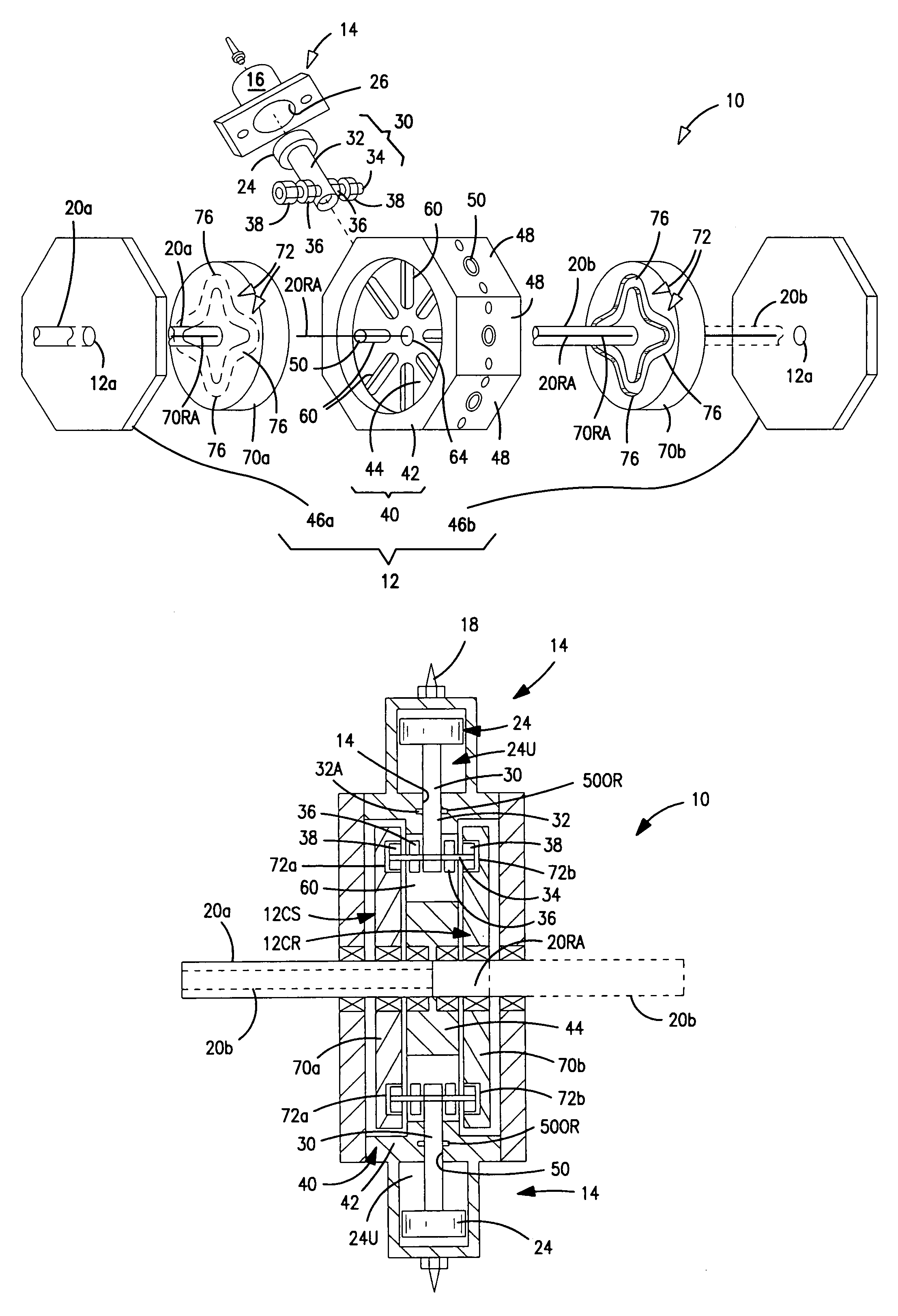
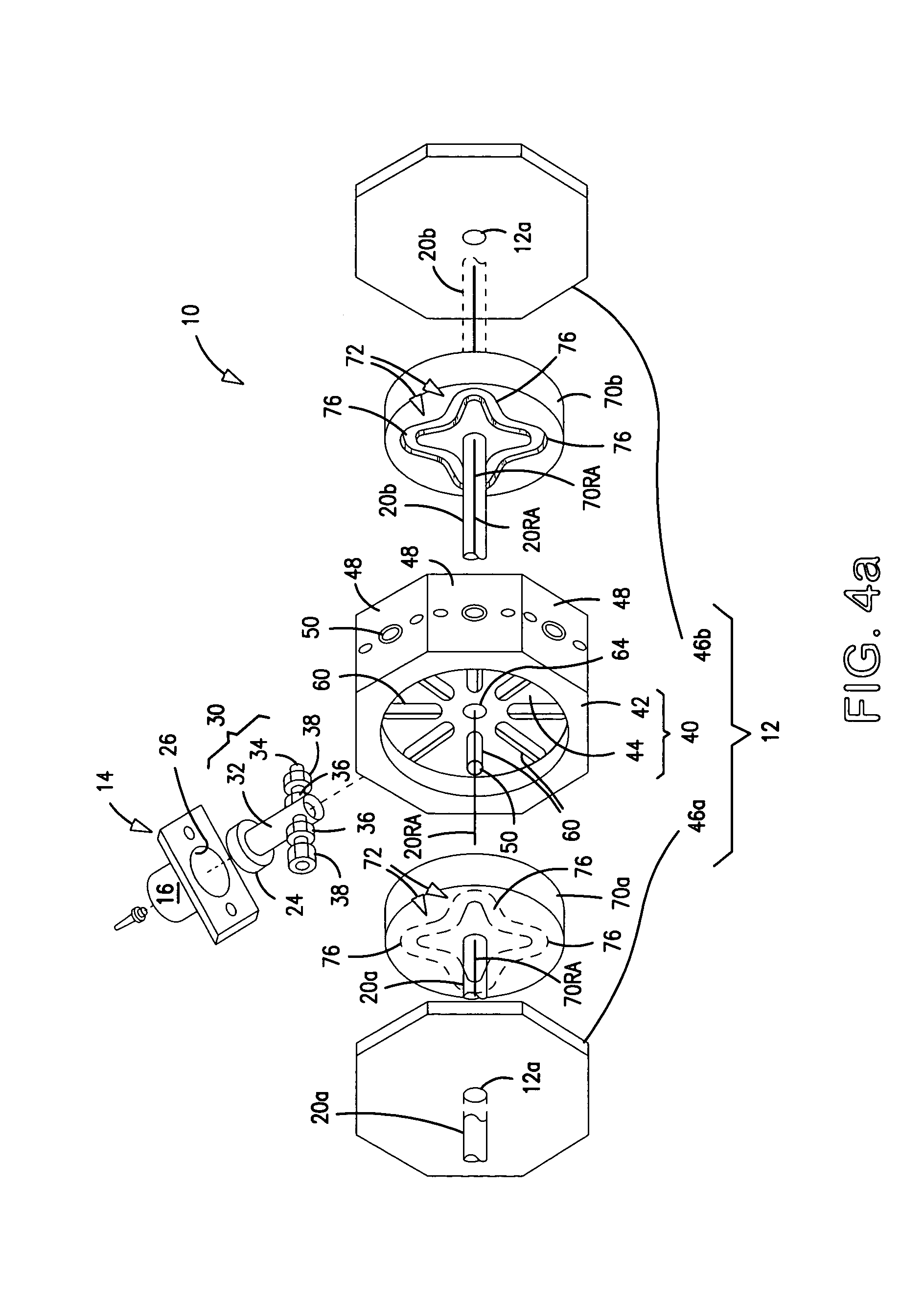
[0048]The present invention relates to a new and useful cam driven Internal Combustion Engine (ICE) that delivers high torque at low rotational velocity. The preferred embodiment is described in the context of eight reciprocating pistons acting on two internal rotating drive cams that, in turn, drive coaxial output shafts. It will be appreciated, however, that the inventive features of the invention may be applied to similar internal combustion engines having fewer or a greater number of reciprocating pistons, to those having more than two cam drives, to those wherein the drive cams rotate in the same or opposite rotational directions, or to those having a single output drive shaft.

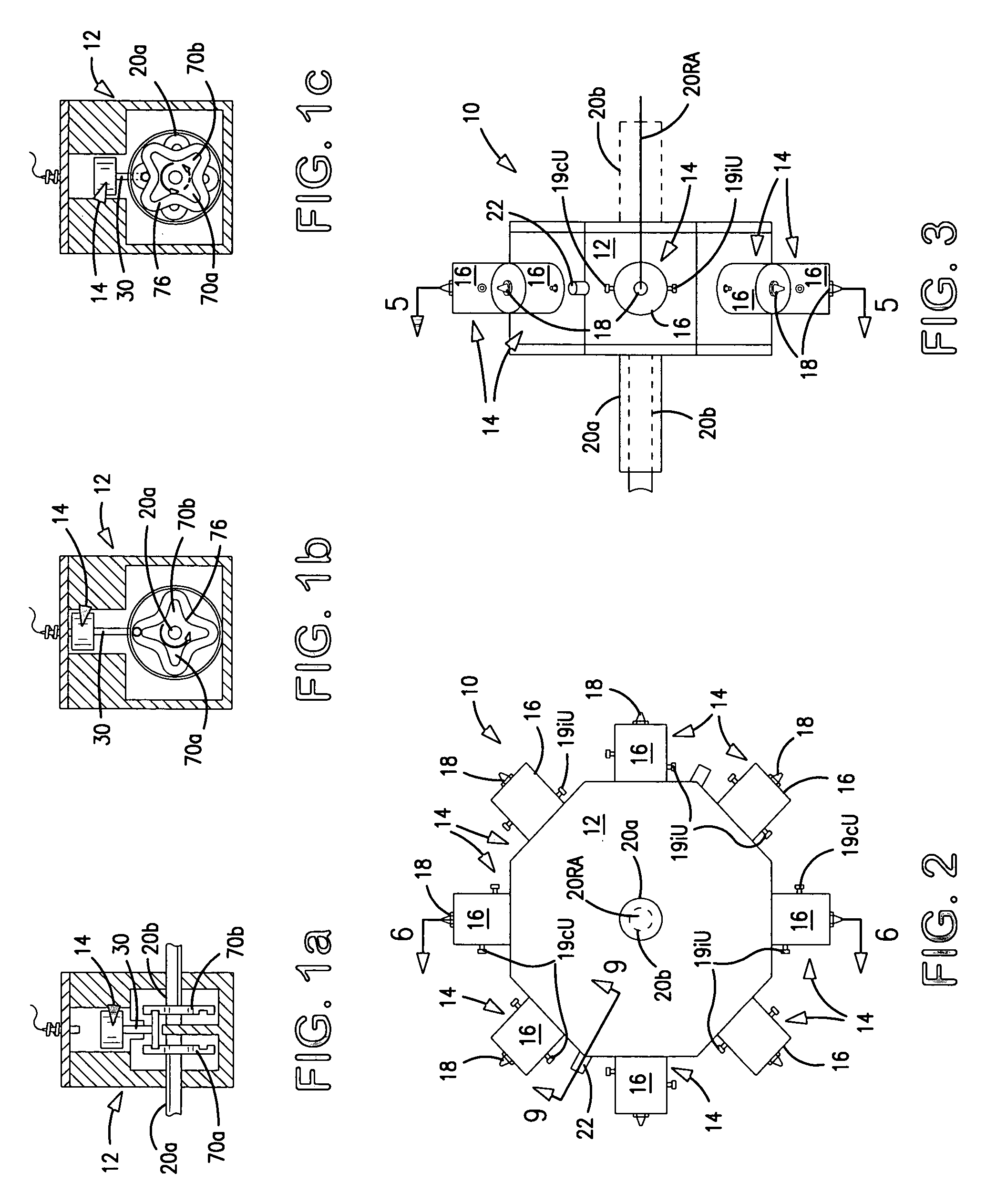
[0049]Before discussing the internal details and specific embodiments of the invention, it is useful to obtain a broad overview of the invention by referring to the schematics shown in FIGS. 1a, 1b, 1c. In the broadest sense of the invention, the ICE comprises a housing 12 which supports: a reciprocating ...


PUM


Abstract

An Internal Combustion Engine including a plurality of reciprocating pistons disposed about the periphery of a central housing, and a pair of drive cams responsive to the displacement of the pistons for driving one or more output drive shafts. A piston rod cross member engages cam raceways of a pair of drive cams. Each raceway comprises a plurality of lobes defining power and compression stroke surfaces. Axial displacement of the cross member within the raceway effects rotation of the drive cams and output drive shafts which are rotational coupled to each drive cam. The drive cams and output drive shafts may rotate in the same or opposite directions, delivering high torque at low rotational speeds and, in one embodiment providing a torque-balanced output. Furthermore, the drive cams may include peripheral teeth for driving a timing gear which is timed relative to the output drive shafts for driving auxiliary equipment.

Description

RELATED APPLICATION[0001]This application is a continuation of U.S. patent application Ser. No. 10 / 371,652, Filed on Feb. 24, 2003 now abandoned and is related to a commonly-owned, US. patent application Ser. No. 10 / 112,145, entitled “Propulsion System for Vertical Take-Off and Landing (VTOL) Vehicles”.TECHNICAL FIELD[0002]This invention is directed to internal combustion engines, and more particularly, to internal combustion engines employing cam means for converting linear motion of a piston / cylinder into rotational motion of an output drive shaft, and still more particularly, to a new and useful internal combustion engine which maximizes energy conversion, eliminates the need for intermediate speed reduction devices, e.g., speed reducing transmissions, improves performance, enhances reliability and reduces mechanical complexity.BACKGROUND OF THE INVENTION[0003]Designers of power output devices, e.g., automobile, aircraft and locomotive engines, are faced with a myriad of competin...

Claims


Application Information

Patent Timeline
IPC IPC(8): F02B75/22F02B57/08F02B57/10F16H25/08F16H25/16F01B13/06
CPCF01B1/062F02B75/222F01B9/06Y10T74/18296
Inventor O'NEILL, JAMES LEO
Owner ONEILL JAMES LEO
Why Eureka
Try Eureka