Eureka AIR delivers breakthrough ideas for toughest innovation challenges, trusted by R&D personnel around the world.

Method for high pressure treatment of substances under controlled temperature conditions

a technology of controlled temperature and treatment method, applied in the direction of pressure vessel for chemical process, pressurized chemical process, disinfection, etc., can solve the problems of reducing the ability of the pressure process to inactivate microorganisms, hotter products and pressure media, etc., to reduce the amount of heat transferred and prevent heat loss

Active Publication Date: 2007-05-22
AVURE TECH
View PDF70 Cites 22 Cited by
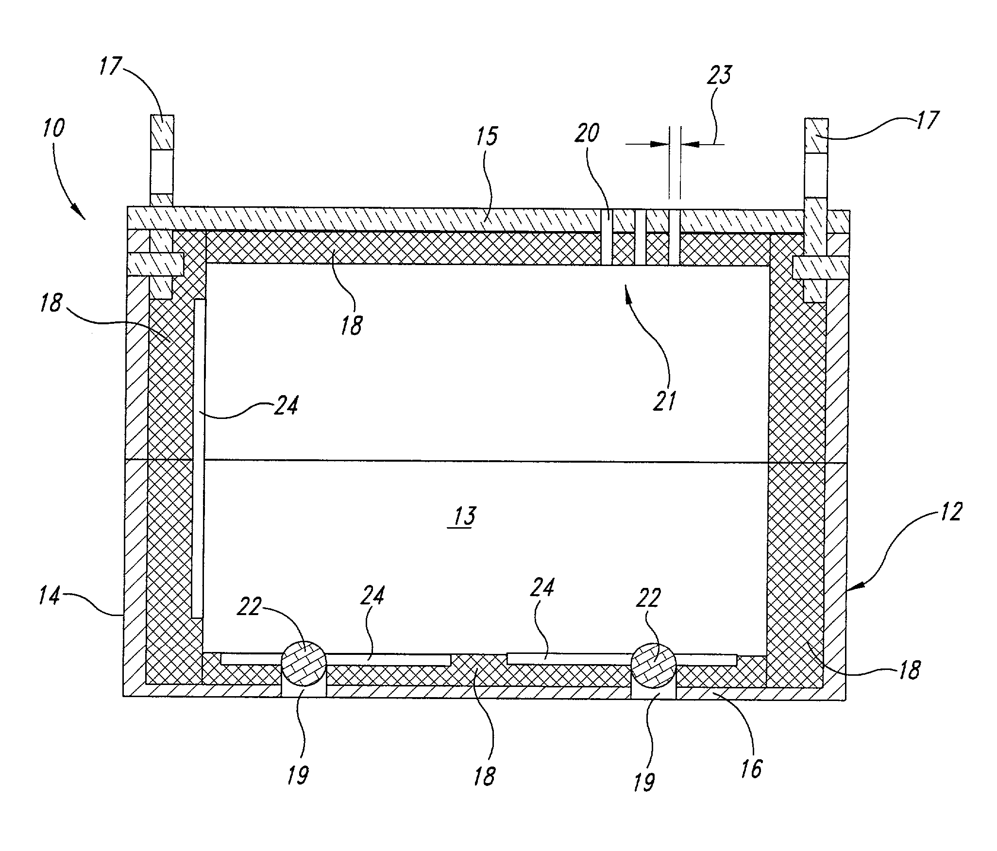
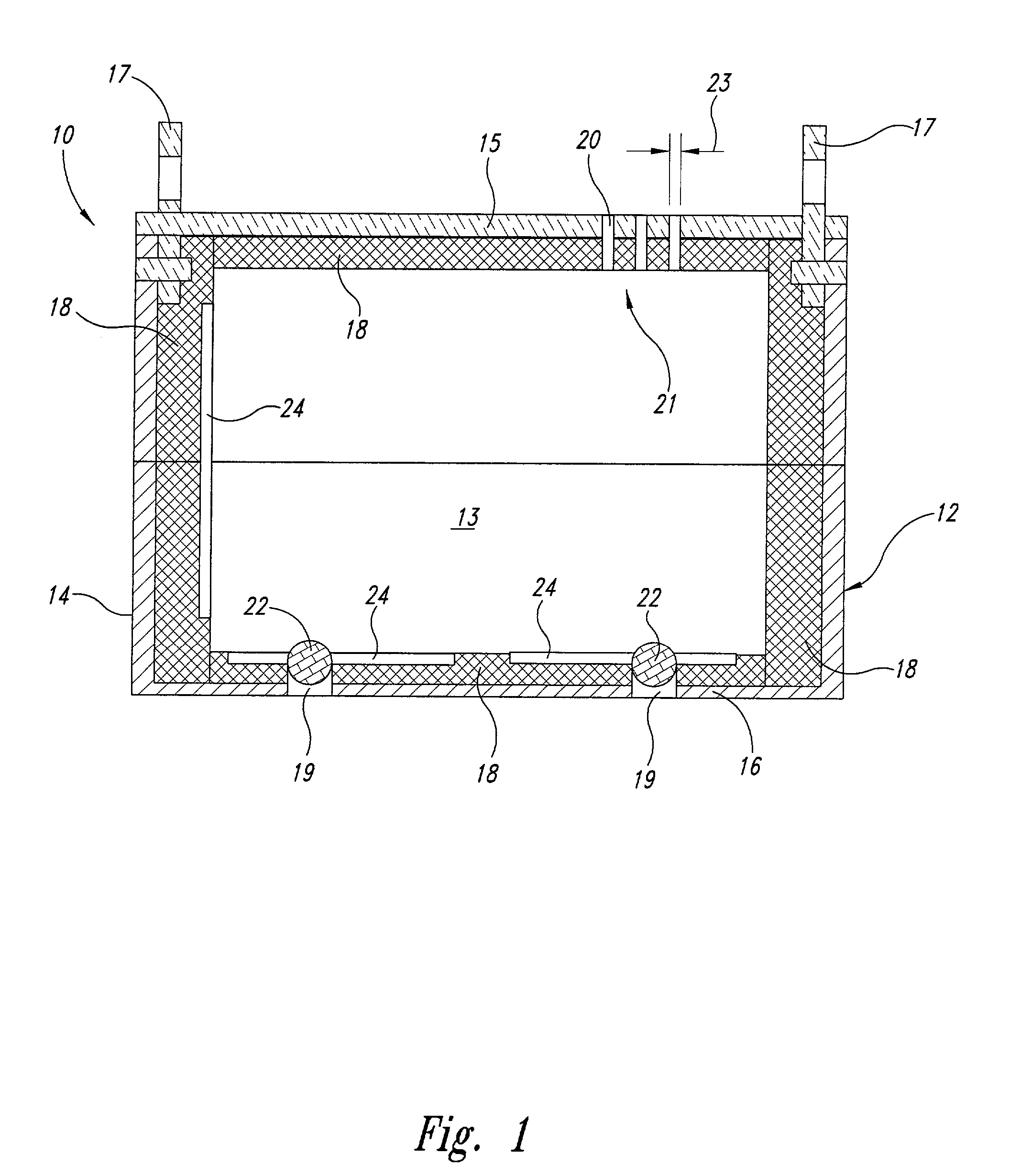
  • Summary
  • Abstract
  • Description
  • Claims
  • Application Information

AI Technical Summary

Benefits of technology

[0005]Briefly, the present invention improves the efficacy of the pressure processing of substances by providing an insulated carrier into which is placed the substance to be treated. Applicants believe that the ability of current methods to inactivate targeted microorganisms, especially difficult ones like bacteria spores, is reduced by the loss of heat from the product to the vessel. More particularly, during the pressurization cycle, the product and pressure media get hotter due to compression or adiabatic heating. Because the walls of the pressure vessel do not experience a similar increase in temperature, there is a temperature difference between the vessel wall and the product under treatment. As a result, heat flows from the product, reducing the ability of the pressure process to inactivate microorganisms.
[0006]Therefore, the present invention improves the efficacy of a pressure treatment process by providing an insulated enclosure into which is placed a substance or product to be treated. The enclosure has solid side walls, a top closure, and a floor that define an outer surface of the enclosure that is substantially fluidically closed. Pressure media entry ports are provided in the enclosure, and in a preferred embodiment, valves are positioned in the ports to selectively allow pressure media to enter the enclosure.
[0007]The enclosure is insulated by providing a quantity of insulating material around an inner region of the enclosure. Any low conductivity material may be used for insulation, for example, polyethylene, polypropylene, polyvinylchloride, or rubber. In a preferred embodiment, the insulating material has substantially high adiabatic heating properties, such that the temperature of the insulation increases during the pressurization cycle. For example, ultrahigh molecular weight polyethylene (UHMWPE), at 25° C. exhibits a compression temperature change of 5° C. per 100 MPa pressure change. Low density polyethylene at 25° C. exhibits an adiabatic compression temperature change of 7° C. per 100 MPa pressure change, and natural rubber at 25° C. exhibits a compression temperature change of 8° C. per 100 MPa pressure change. By insulating the product carrier, heat loss from the product chamber to the metal pressure vessel is substantially minimized during the pressure cycle. Using an insulating material with high adiabatic heating properties generates a temperature barrier to further prevent heat transfer from the product chamber to the vessel wall. Also, by using a carrier that is substantially fluidically closed, as compared to conventional perforated baskets, the circulation of pressure media from the product to the vessel wall is substantially prevented.
[0009]In another preferred embodiment, the pressure vessel is preheated to a temperature that is higher than the starting temperature of the product prior to pressurization. Assuming certain pressure characteristics of the substance being treated, the vessel is preheated to a temperature the product is expected to reach upon being pressurized. A high vessel wall temperature will prevent heat loss from the product. The presence of the insulating carrier will reduce the amount of heat transferred to the product prior to the start of pressurization.

Problems solved by technology

More particularly, during the pressurization cycle, the product and pressure media get hotter due to compression or adiabatic heating.
As a result, heat flows from the product, reducing the ability of the pressure process to inactivate microorganisms.

Method used


Image

  • Method for high pressure treatment of substances under controlled temperature conditions
  • Method for high pressure treatment of substances under controlled temperature conditions
  • Method for high pressure treatment of substances under controlled temperature conditions

Examples


Embodiment Construction

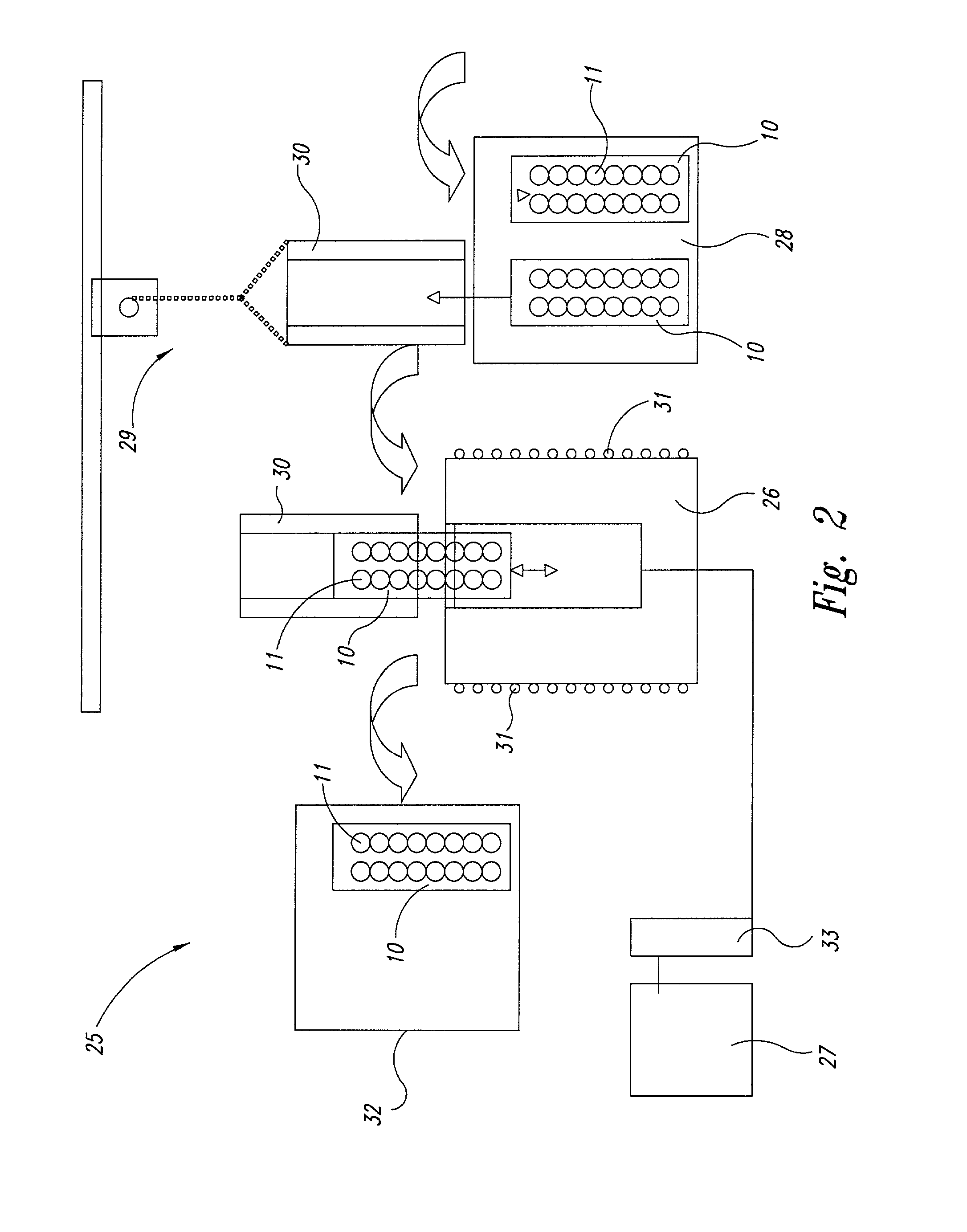
[0012]Many objectives may be achieved by exposing a substance to ultrahigh-pressure. Such pressure processing may be used, for example, to pasteurize or sterilize a substance, such as a medical or food product. Although the selected pressure will vary depending on the application, pressures in the range of 40,000-130,000 psi are often used and thought of when referring to ultrahigh-pressure processing. It will be understood that other variables in the process are also selected according to the application, as determined by one of ordinary skill in the art. These other variables include such things as the temperature at which the substance is processed and the amount of time the substance is held under pressure, commonly referred to as the dwell time.

[0013]Current pressure processing of a substance, for example, to destroy microorganisms, can be done in a continuous flow process or in batches. In conventional batch processing, the product or substance to be pressure treated is placed...


PUM

PropertyMeasurementUnit
Temperatureaaaaaaaaaa
Pressureaaaaaaaaaa
Temperatureaaaaaaaaaa

Abstract

A product carrier for use in pressure processing substances is substantially fluidically closed, and is insulated, to prevent heat transfer from the product being treated to the cooler wall of the pressure vessel. The insulating material has compression heating properties, such that as the product is pressurized, the temperature of the insulation increases as does the temperature of the product and pressure media, thereby helping to prevent heat transfer from the product to the surrounding media and pressure vessel wall.

Description

TECHNICAL FIELD[0001]This invention relates to the high pressure treatment of substances, for example, food products, and more particularly, to the high pressure treatment of substances under controlled temperature conditions.BACKGROUND OF THE INVENTION[0002]It is well known that pathogens and microorganisms in substances, for example, food, may be inactivated by exposing the substances to high pressure. It is also well understood that for some applications, for example, for microorganisms that are difficult to inactivate, the effectiveness of the pressure processing can be enhanced by the use of elevated temperatures.[0003]Using currently available systems and methods, a substance to be treated is placed in a container, typically a perforated basket made from stainless steel or plastic. The perforated basket and its contents are placed into a pressure vessel and exposed to a pressure media, typically high pressure water, for a selected period of time. The pressure vessel is then de...

Claims


Application Information

Patent Timeline
IPC IPC(8): A61L2/02A23L3/015A61L2/00A61L2/04A61L2/26B01J3/00B01J3/03
CPCA23L3/0155A61L2/0011A61L2/02A61L2/26
Inventor TING, EDMUND Y.LONNEBORG, NILS-GUNNARTRAFF, ANDERS
Owner AVURE TECH
Why Eureka
Eureka Blog
Learn More