Heat dissipating pin structure for mitigation of LED temperature rise
a heat dissipation pin and temperature rise technology, applied in the direction of electrical equipment construction details, lighting and heating apparatus, transportation and packaging, etc., can solve the problems of heat rising, led being permanently damaged, and presenting a phenomenon of temperature rise, so as to improve the heat dissipation capability of densely arranged and improve the quality of led.
- Summary
- Abstract
- Description
- Claims
- Application Information
AI Technical Summary
Benefits of technology
Problems solved by technology
Method used
Image
Examples
embodiment 1
[0017]
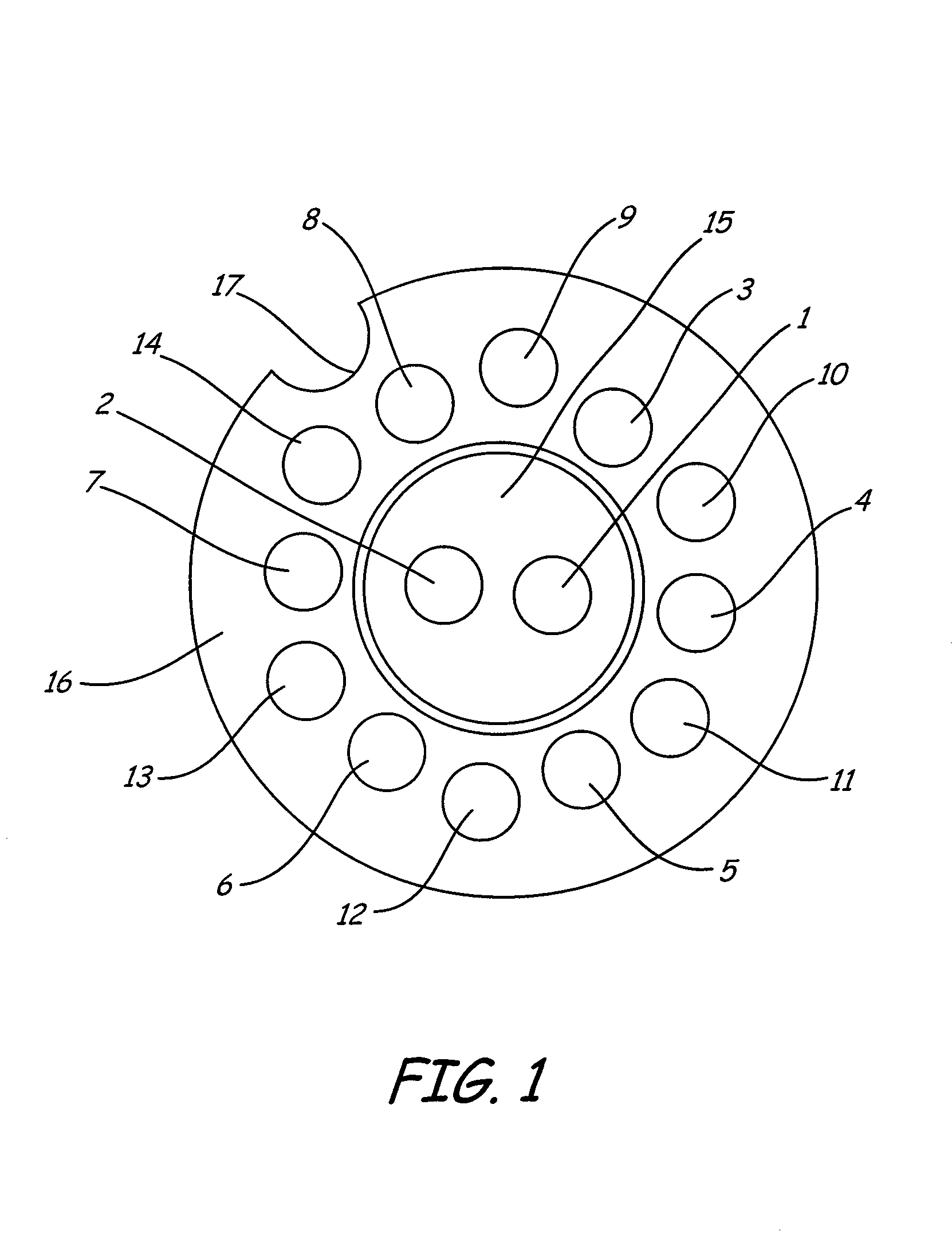
[0018]FIG. 1 shows layout view of a PCB of LED light of 5 mm in diameter with 6 LED chips, in which 6 LED chips being in parallel connection Metallic pins of Φ 0.46×10.24 mm are led out through holes 1–8 respectively, wherein holes 1–2 are used for two pinouts of same polarity of LED, and holes 3–8 are used for 6 pinouts of another polarity of LED. Holes 9–14 are used as running holes for encapsulation of epoxy resin and no metallic pins are led out from there. Reference numerals 15 and 16 denote copper foil surfaces of PCB, on which metallic pins are riveted perpendicularly. Numeral 17 is a gap for positioning. In this embodiment, above said 8 heat-dissipating pins also serve for electric pinouts, and 6 LED chips are directly secured on top ends of No. 3–8 heat-dissipating pins by means of brazing technique, so that top end of each LED chip is electrically connected to copper foil surface 15, wherein pin 1–2 serve for electric pinouts. Heat generated after energizing of said ...
embodiment 2
[0019]
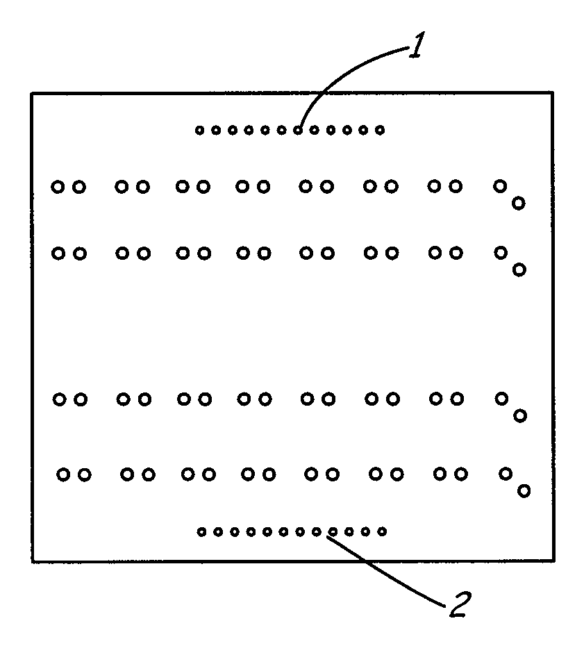
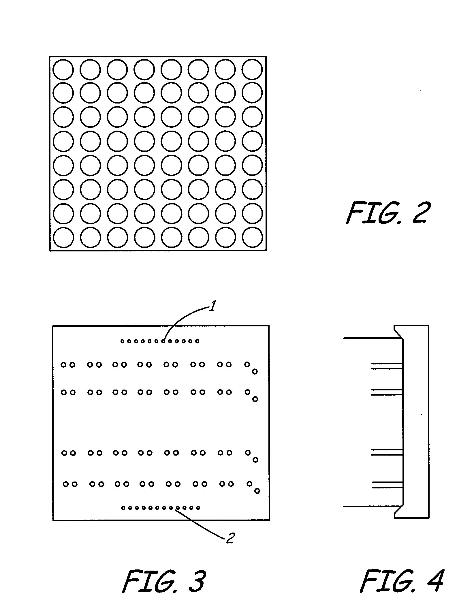
[0020]FIG. 2 shows front view of a bi-color LED matrix display module with 8×8 pixels of 10 mm spacing (face of reflection chamber set). FIGS. 3 and 4 show back view (PCB back face) and side view of FIG. 2 respectively, wherein reference numeral 1 and 2 in FIG. 3 denote two rows of pinouts (12 in each tow), and in remaining 4 rows 16 heat-dissipating pins are arranged in each row, wherein the rightmost pin is staggered in position due to limitation in arrangement of PCB. According to the circuit layout and the need of heat-dissipation, heat-dissipating pins of same column in present embodiment are connected in same polarity in electric circuit, but heat-dissipating pins of different columns should not be in contact to avoid short circuit.
[0021]It can be seen from FIG. 4 that all heat-dissipating pins are shorter than electric pinouts. When electric pinouts of displaying module are brazed on corresponding driving PCB, all heat-dissipating pins are exposed outside and not in con...
PUM
 Abstract
Description
Claims
Application Information
 - R&D
- Intellectual Property
- Life Sciences
- Materials
- Tech Scout
- Unparalleled Data Quality
- Higher Quality Content
- 60% Fewer Hallucinations
Browse by: Latest US Patents, China's latest patents, Technical Efficacy Thesaurus, Application Domain, Technology Topic, Popular Technical Reports.
© 2025 PatSnap. All rights reserved.Legal|Privacy policy|Modern Slavery Act Transparency Statement|Sitemap|About US| Contact US: help@patsnap.com


