Operating a vehicle with braking energy recovery

Inactive Publication Date: 2007-06-19
SCHECHTER MICHAEL MOSES
View PDF11 Cites 94 Cited by
  • Summary
  • Abstract
  • Description
  • Claims
  • Application Information

AI Technical Summary

Benefits of technology

[0049]A further object of the present invention is to reduce or eliminate the need for electric starter b

Problems solved by technology

Turbocharging the compression-braking mode of engine operation leads to a substantial increase in the mass of the air charge the engine receives from outside atmosphere during each compression-braking cycle.
This increases the negative work-per-cycle and thus increases the vehicle braking torque the engine can provide.
This often requires very short duration of the engine valve-opening event, especially during the second stage of compression or the first stage of expansion.
In many instances, however, this solution is impractical, because keeping the

Method used


Image

  • Operating a vehicle with braking energy recovery
  • Operating a vehicle with braking energy recovery
  • Operating a vehicle with braking energy recovery

Examples


Embodiment Construction

FIGS. 1 to 3 and 26

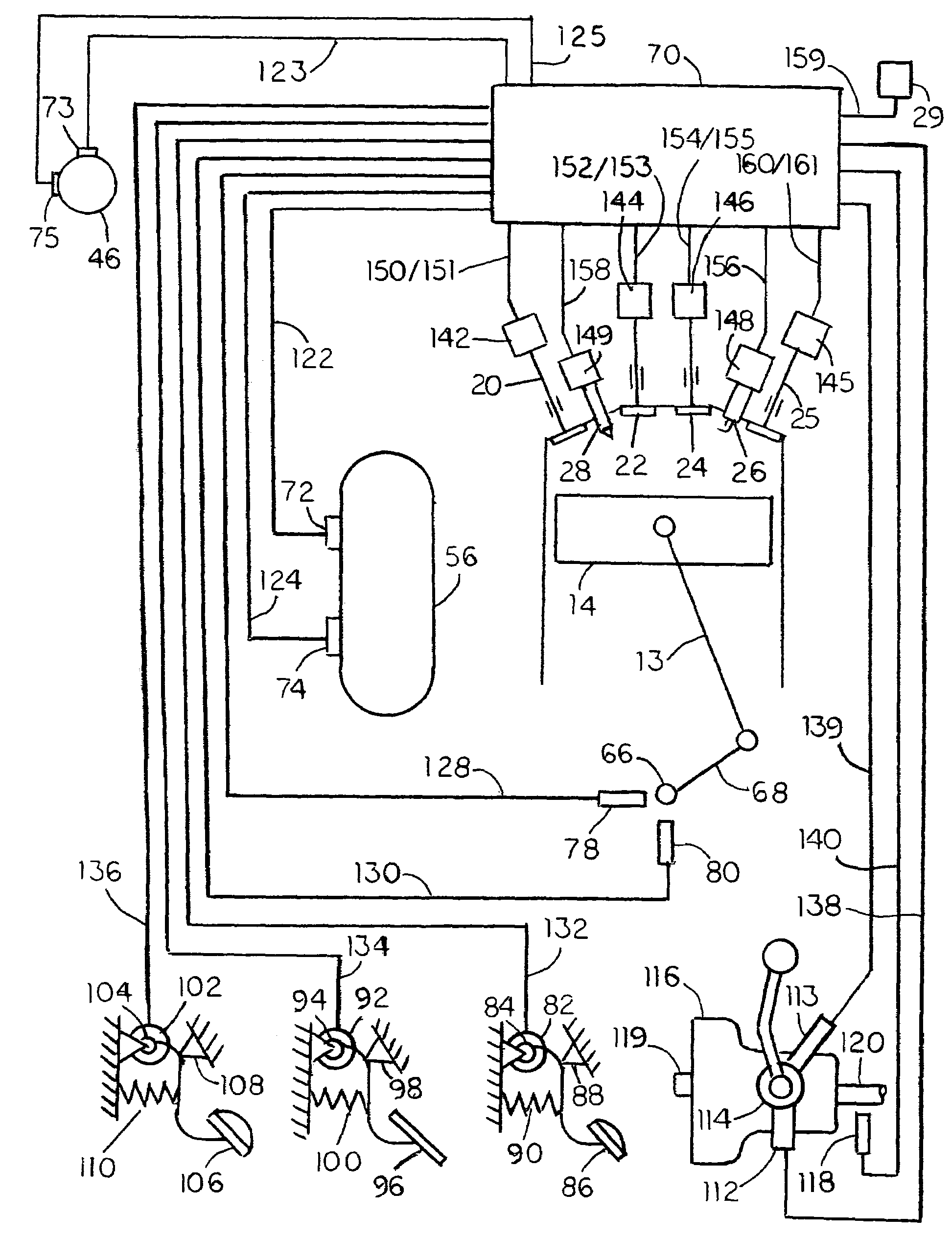
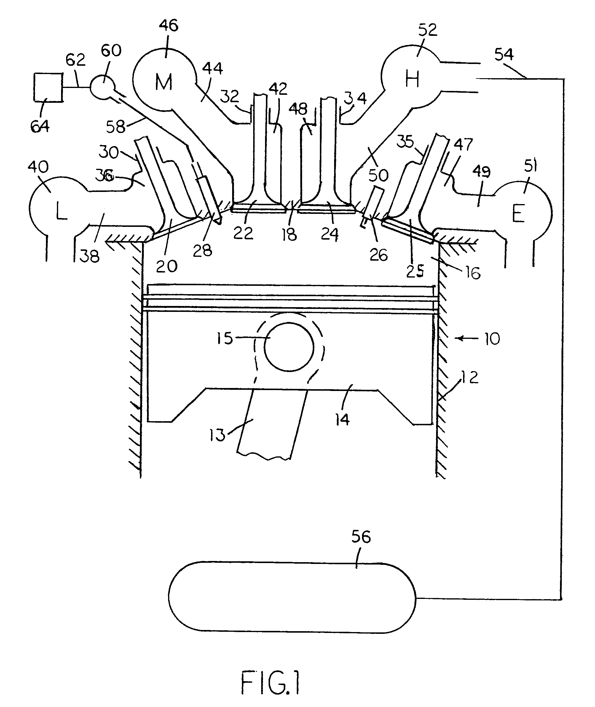
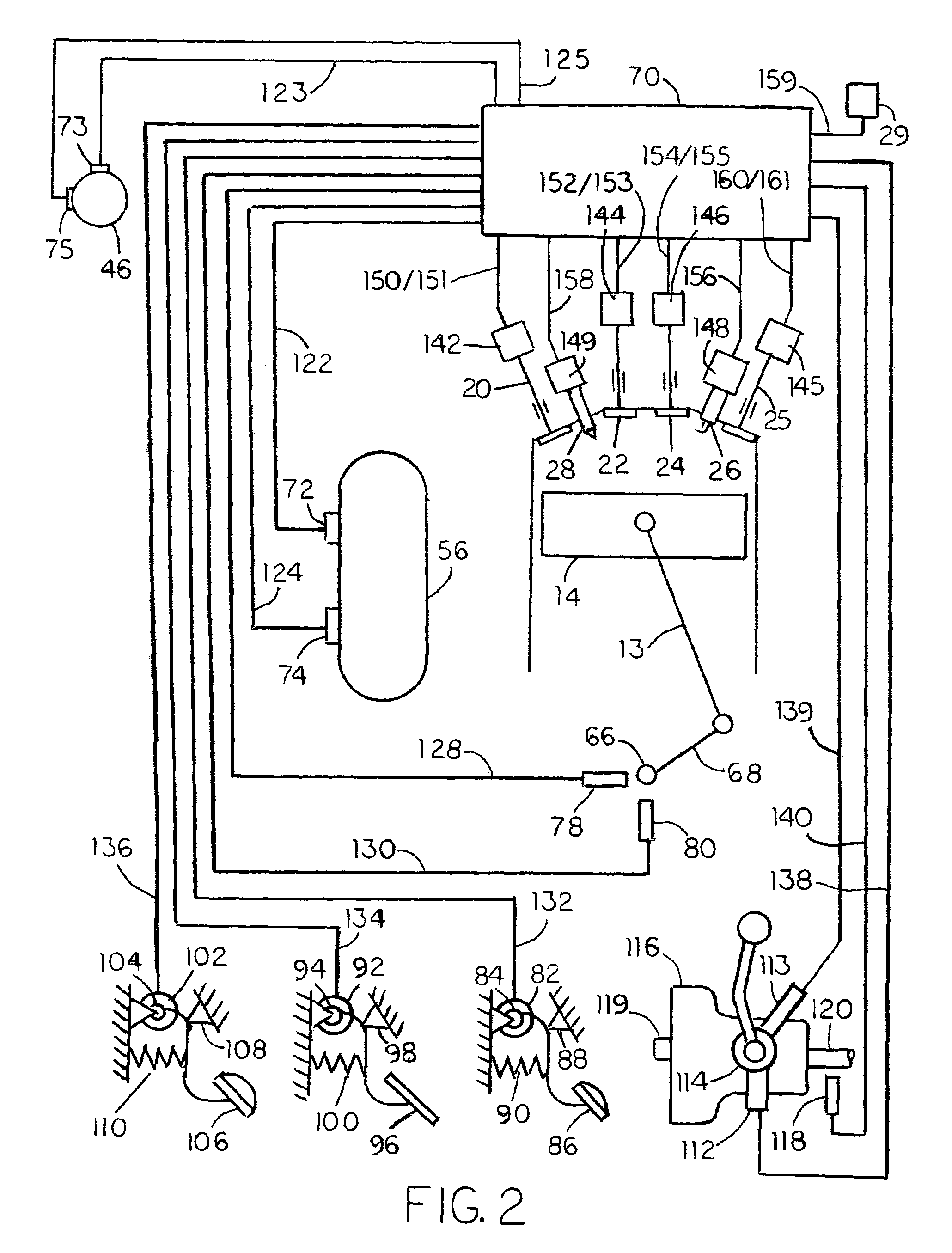
[0098]A preferred embodiment of the present invention is illustrated in FIGS. 1 to 3. FIG. 1 is a schematic, cross-sectional side-view of an engine cylinder and head arrangement and its connection to a compressed-air reservoir. An engine 10 has at least two such cylinders. A cylinder 12 contains a piston 14, which is mounted upon a connecting rod 13 by a wrist pin 15 and can reciprocate in cylinder 12, thus varying the volume of a cylinder chamber 16 enclosed between piston 14 and a cylinder head 18 attached to the top of cylinder 12.

[0099]Four types of normally-closed valves, a first valve 20, a second valve 22, a third valve 24, and a fourth valve 25, are installed in cylinder head 18. Valves 20, 22, 24, and 25 are slidably mounted in guides 30, 32, 34, and 35, respectively, which are arranged in cylinder head 18. Depending on the needs of the engine, there may be more than one valve of each type in each engine cylinder. A conventional spark plug 26 and a fuel i...


PUM


Abstract

A vehicle engine has a system of valves that permits various engine cylinders to operate in different modes of operation. During braking, some of the engine cylinders receive atmospheric air, compress it, and transfer it to an intermediate air-container. Other cylinders receive compressed air from the intermediate air-container, further compress it, and transfer it to a high-pressure air-reservoir for storage. During acceleration, some of the engine cylinders receive compressed air from the high-pressure air-reservoir, expand it to a lower level of pressure, and transfer it to the intermediate air-container. Other cylinders receive air from the intermediate air-container, further expand it, and use it for combustion in an internal-combustion cycle. During short stops, the engine is shut down, for the duration of the stop, and, then, it is restarted with compressed air. During cruise, the engine operates as a conventional internal-combustion engine.

Description

CROSS-REFERENCE TO RELATED APPLICATIONS[0001]Not ApplicableFEDERALLY SPONSORED RESEARCH[0002]Not ApplicableSEQUENCE LISTING OR PROGRAM[0003]Not ApplicableFIELD OF THE INVENTION[0004]The present invention relates to vehicle systems capable to accumulate energy derived from vehicle motion during its deceleration or obtained from operation of the vehicle engine, and use the accumulated energy to assist in vehicle acceleration and propulsion at a later time.BACKGROUND OF THE INVENTION[0005]Most automotive vehicles are propelled by internal combustion engines consuming hydrocarbon fuels. Burning these fuels produces exhaust gas containing harmful air-pollutants, such as carbon monoxide, nitrogen oxides, and unburned hydrocarbons. It also contains substantial amount of carbon dioxide which, if produced in large quantities worldwide over long period of time, can contribute to an undesirable increase in average global temperature. Concern for clean air and a desire to prevent adverse conseq...

Claims


Application Information

Patent Timeline
IPC IPC(8): B60K6/12
CPCB60K6/12F02D13/0261F02N9/04F02D41/0087F02N11/0814Y02T10/6208Y02T10/18Y02T10/12Y02T10/62
Inventor SCHECHTER, MICHAEL MOSES
Owner SCHECHTER MICHAEL MOSES
Why Eureka
Try Eureka