Throw-away tip

Active Publication Date: 2007-06-26
KYOCERA CORP
View PDF20 Cites 25 Cited by
  • Summary
  • Abstract
  • Description
  • Claims
  • Application Information

AI Technical Summary

Benefits of technology

[0016]The recess (chip breaker groove) is substantially V-shaped such that the bottom is a steep slope on the land surface side and is a gentle slope on the central surface side. The recess is also formed to have as small width as possible. This makes it possible to properly warp and break chips and discharge the chips smoothly out of

Problems solved by technology

As a result, seating of the throw-away tip 21 becomes insecure thus leading to vibration of the corner 33 during cutting operation.
The throw-away tip 21 of full-circumference chip breaker, however, also has such a problem that, in case the land 25 of the rake face is damaged due to chipping of the edge 24 or a crater wear during cutting operation with one side of the throw-away tip, the damaged land 25 at a corner portion 33 that has the greatest effect on seating of the throw-away tip 21 cannot provide satisfactory seating surface when the throw-away tip 21 is turned over.
As a result, stability of seating is lowered while undesirable movements of the throw-away tip 21 such as lifting and chattering vibration cannot be suppressed and causing such problems as tool damage and/or rough machined surface.
There is also such a problem that, the longer the land surface on one side of the principal surface, the lower the rigidity and more susceptible to deflection.
Particularly when used in a cutting operation under conditions involving severe impact, deflection of the land surface causes chattering vibration which ma

Method used


Image

  • Throw-away tip
  • Throw-away tip
  • Throw-away tip

Examples


example i

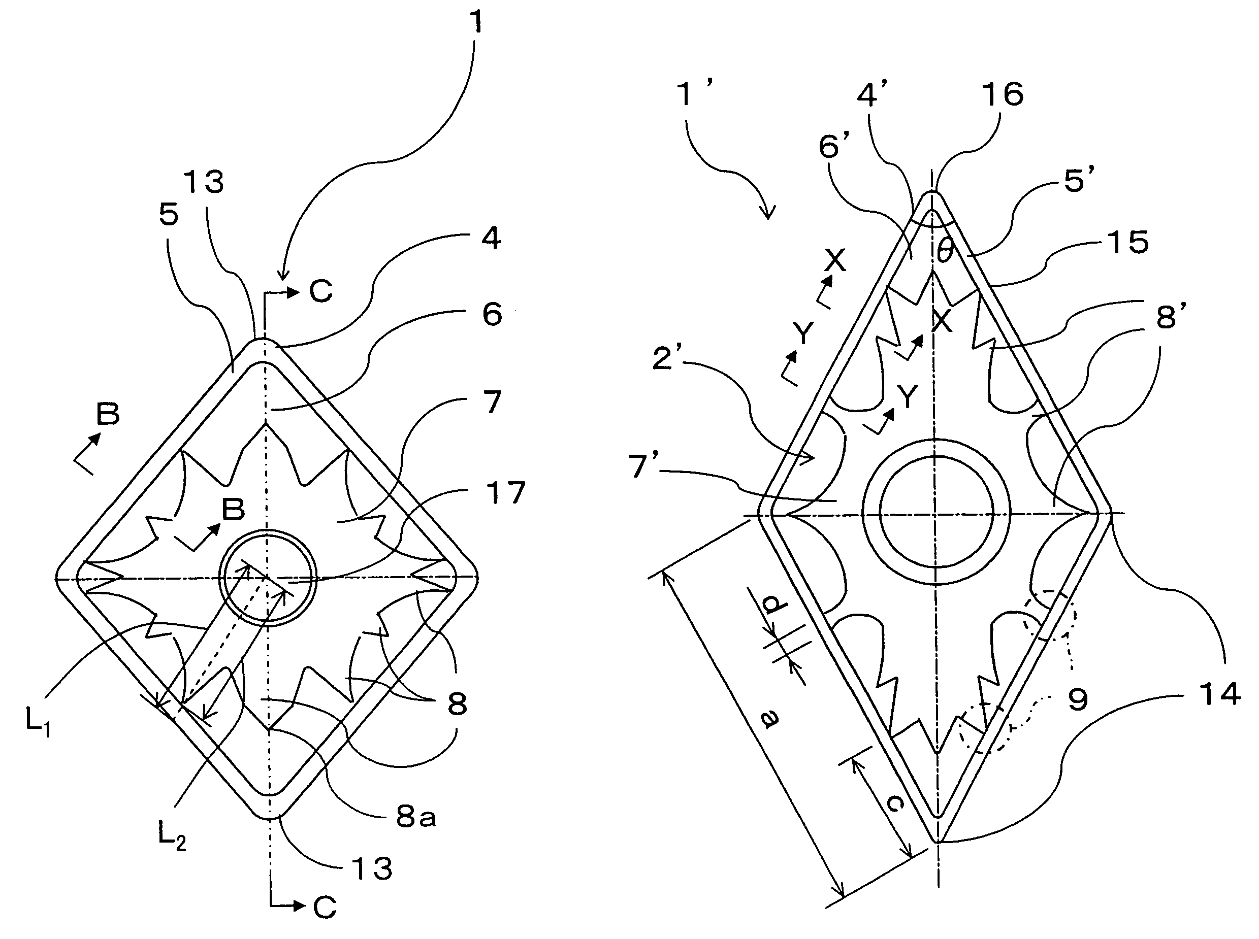
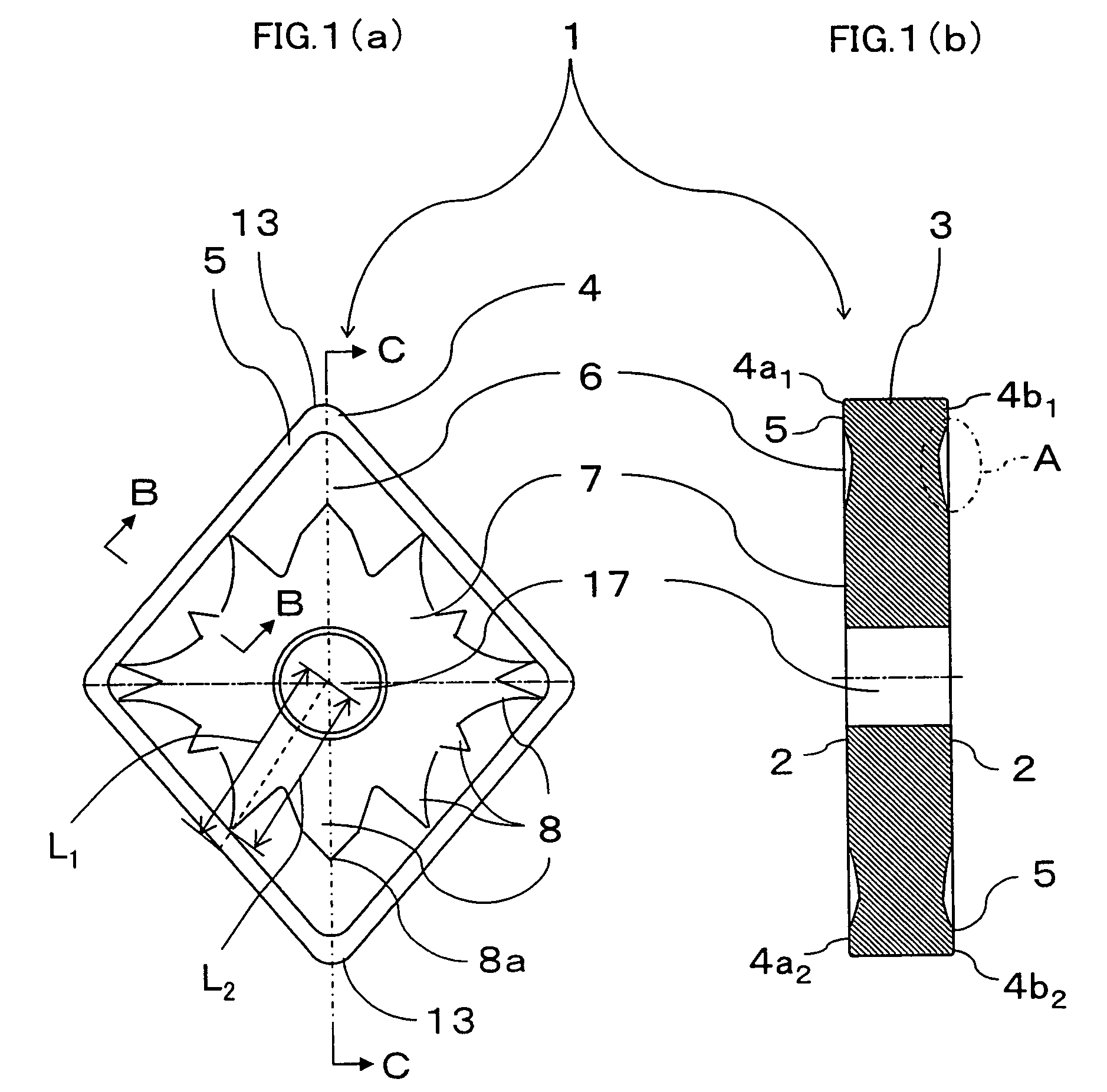
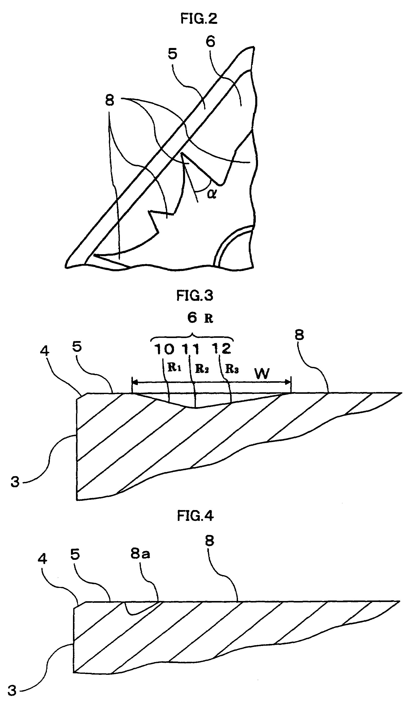
[0075]A mixed powder prepared by adding 11% by weight of Co to WC powder was pressed to form green compacts of types and specifications shown in Table 1 each having two noses on each side, four noses in all. After being sintered in vacuum, samples I-1 through 6 were ground on the central surface and on the land surface of each principal surface to make the height of the central surface and the height of the land surface equal. In samples I-1 through 6 and 8 through 11, central surfaces were formed so as to protrude in symmetrical configurations at opposing corners, while forming a slope of 45° at the distal end setting the clearance (w) between the distal end of the projection of the central surface and the land surface to 0.2 mm, so that variation in the parallelism during the grinding process could be monitored visually.

[0076]Sample No. I-7 was formed in the conventional shape without chip breaker, samples No. I-8, 9 were formed in the conventional shape where the land surface is ...

example ii

[0087]A mixed powder prepared by adding 11% by weight of Co to WC powder was pressed to form green compacts that would make sintering of the shapes and dimensions shown in FIGS. 5, 7 and Table 3. After being sintered in vacuum, samples II-1 through 4 were ground on the central surface and on the land surface of each principal surface so as to make the height of the central surface and the height of the land surface equal. Samples II-1 through 8 were formed in diamond shape having nose angle θ of 55° with a linkage portion formed (FIG. 5). Sample No. II-5 was formed in the conventional shape without chip breaker as shown in FIG. 7(a), sample No.II-6 was formed in such a shape that has full-circumference chip breaker while the land surface has the same height as the central surface, without protrusion as shown in FIG. 7(b), and samples No. II-7, 8 were formed in a shape without linkage portion as shown in FIG. 7(c).

[0088]All samples were processed on the periphery of the land surface ...

example iii

(Example III-1)

[0096]A mixed powder prepared by adding 11% by weight of Co to WC powder was pressed to form green compacts of types and dimensions shown in Table 5 having such a pattern as shown in FIG. 8. After being sintered in vacuum, the central surface and the land surface were ground (double-head grinding) on each principal surface to make the height as shown in Table 1 (samples Nos. III-1 through 10).

[0097]When grinding the throw-away tips, the protrusions 8A located at the corners 13″ were formed at a distance (w) of 0.2 mm from the protrusion 8A to the land surface in such a shape as to form a downward slope of 45° from the protrusion 8A to the land surface, while setting the clearance (w) between the distal end of the projection and the land surface being monitored visually when grinding the surface, thereby making it possible to achieve machining with high accuracy easily. The samples were processed on the periphery of the land surface to provide honed edge using a brush,...


PUM

PropertyMeasurementUnit
Lengthaaaaaaaaaa
Fractionaaaaaaaaaa
Angleaaaaaaaaaa

Abstract

A throw-away tip of which two principal surfaces each has a land surface provided along the periphery thereof, a central surface provided on the inside of the land surface, a recess (a chip breaker groove) interposed therebetween, and at least one protrusion that extends from the central surface toward the land surface, wherein height of the land surface is made equal to the height of at least the top surface of the protrusion so that at least the top surface of the protrusion of the central surface and the land surface both serve as contact surface is provided.

Description

BACKGROUND OF THE INVENTION[0001]1. Field of the Invention[0002]The present invention relates to a throw-away style cutting tip used for cutting a cast iron and a steel.[0003]2. Description of Related Art[0004]Throw-away style cutting tips have been used for cutting a cast iron and a steel. Throw-away tips that have modified rake face configurations have been known, such as those having a chip breaker formed in the rake face so as to protect the rake face from being damaged by removed metal chips, and those having a land formed near a cutting edge along the periphery of the rake face in order to prevent damage from cutting resistance or the like.[0005]Throw-away tips having chip breakers and lands formed on both sides have such an advantage as both sides can be used in cutting operations. When such a throw-away tip has the cutting edge on one side worn out, the throw-away tip is turned over so as to carry out cutting operation using the cutting edge on the opposite side. A throw-awa...

Claims


Application Information

Patent Timeline
IPC IPC(8): B23B27/16B23B27/14
CPCB23B27/141B23B2200/0428B23B2200/0476Y10T407/235B23B2200/323Y10T407/24Y10T407/23B23B2200/049Y10T83/9319
Inventor ISHIDA, TAKUYA
Owner KYOCERA CORP
Why Eureka
Try Eureka