Optical protection switching using 2 by 2 switching functions

a technology of optical protection switching and switching functions, applied in the direction of transmission monitoring, frequency-division multiplex, instruments, etc., can solve the problems of network upgrade difficulty and high cost of network soot system, so as to reduce the likelihood of a misconnection, reduce the labor involved, and reduce the cost per port

Inactive Publication Date: 2007-07-10
HITACHI AMERICA
View PDF10 Cites 19 Cited by
  • Summary
  • Abstract
  • Description
  • Claims
  • Application Information

AI Technical Summary

Benefits of technology

[0009]It has been thought that single unit optical switches with as many inputs and outputs as possible is a good investment, because the cost per port decreases as the number of ports in a single switch increases. However, the inventor has compared this cost with the observation that the connection of individual fibers to a switch is done by hand and is very difficult. This hand repair results in many wrong and unsatisfactory connections of the extremely fine fibers, which is found to be the major cause of line failure. Therefore, as a part of the present invention, a solution is to use a switch with a small number of ports rather than a switch with a large number of ports, to correspondingly reduce the likelihood of a misconnection and to reduce the labor involved. This solution of the present invention is far more cost effective in the long run than using large switches. Particularly, the 2×2 optical switch has an advantage of ease in handling for both original installation and replacement for upgrading or repair compared with a switch having a far greater number of ports.
[0010]The above solution of the present invention provides flexibility in connecting the small switches. This solution of the present invention involves a connection arrangement for a large number of lines with the use of switches that have few ports, which at first appears to involve conflicting requirements according to the prior art teachings.
[0011]It is known to use a switch with a large number of ports to gain a low cost per port. But, if a 32×32 switch is used for only 6 ports, for example, the cost per usable port has increased substantially over the cost per available port. The present invention that configures multiple low port number switches avoids this problem.
[0012]One can only imagine the extremely tedious replacement of a 128×128 switch that involves at least 256 hand connections of the extremely fine optical fibers. Then, it is easy to understand that the main cause of failure is found to be a misconnection of the fibers due to inaccurate or incomplete manual fiber connections. Therefore, a large switch has a low port cost, but a high cost of installation and a high line failure rate.
[0013]Further, it is desirable to provide for ease of configuration and flexibility of configuration, because a change in network topology flows from unpredictable traffic patterns. Therefore, future flexibility of a system constructed according to the present invention is an advantage.

Problems solved by technology

However, SONET systems are expensive for networks that only need a protection capability and do not need the many additional functions of a SONET system.
Moreover, the SONET system is not easy to upgrade for point-to-point communications, 1:N switching and ring topology, which thereby requires that an existing SONET system must be replaced when the topology is changed.

Method used


Image

  • Optical protection switching using 2 by 2 switching functions
  • Optical protection switching using 2 by 2 switching functions
  • Optical protection switching using 2 by 2 switching functions

Examples


Embodiment Construction

[0039]A switching module, system, method and software for cost effective and flexible configuration network protection are described. In the following description, for the purposes of explanation, numerous specific details are set forth in order to provide a thorough understanding of the present invention. It is apparent, however, to one skilled in the art that the present invention may be practiced without these specific details or with an equivalent arrangement. In other instances, well-known structures and devices are shown in block diagram form in order to avoid unnecessarily obscuring the present invention.

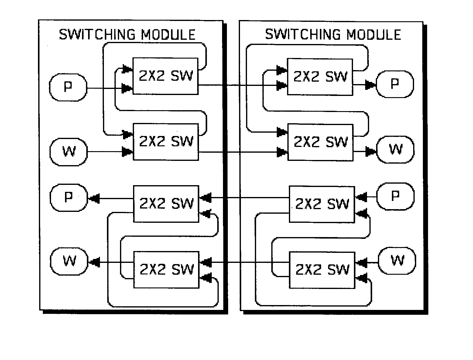
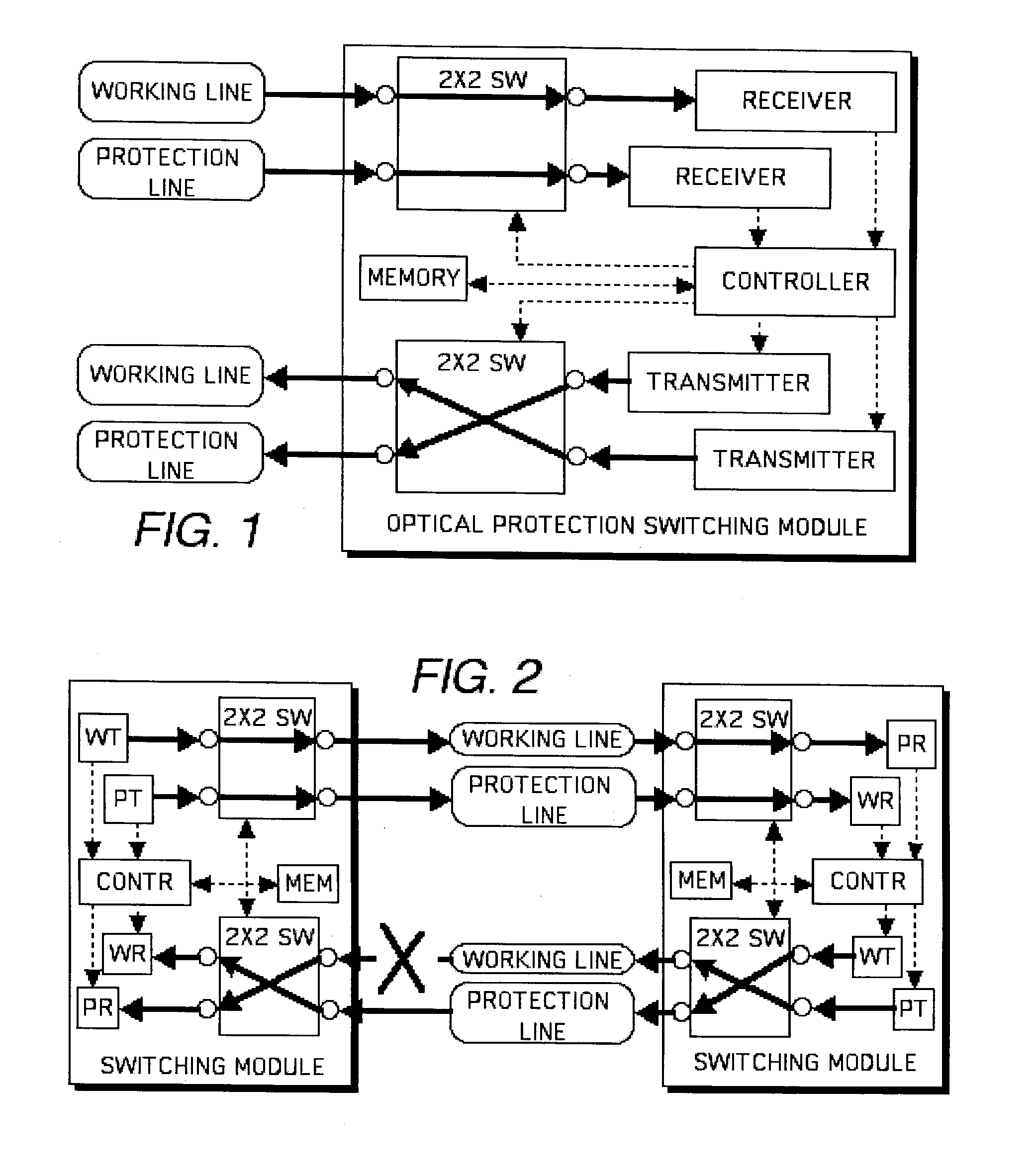
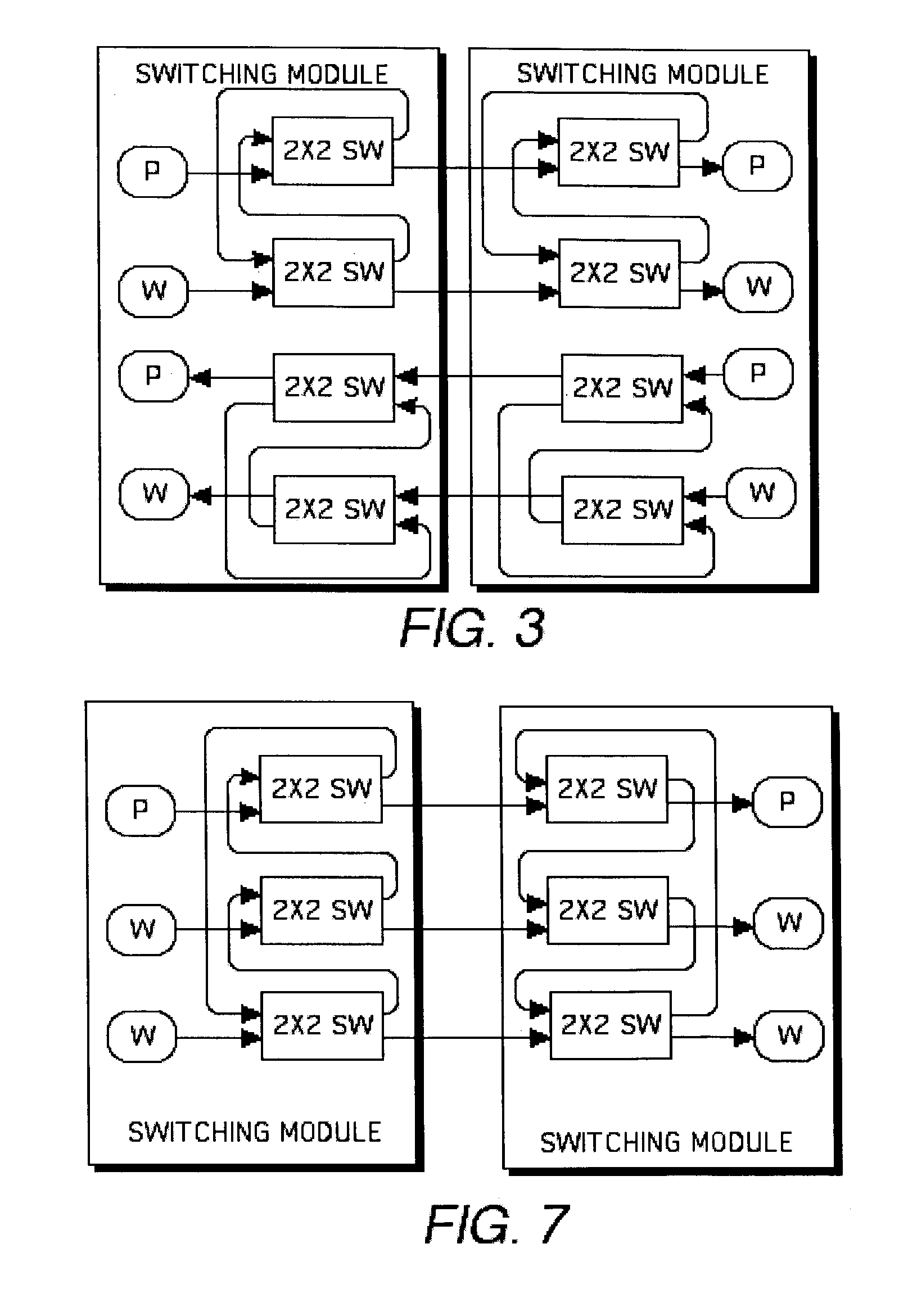
[0040]The preferred embodiment satisfies the above-mentioned needs by solving the mentioned problems for optical network protection by using 2×2 optical switches, or other small switches, which are connected to improve the flexibility, cost effectiveness, availability and reliability of a network. Switches with a greater number of input or output ports than two may be used ac...


PUM

PropertyMeasurementUnit
flexibleaaaaaaaaaa
flexibilityaaaaaaaaaa
optical switchingaaaaaaaaaa

Abstract

A network is protected against interruption of service while one or more faulty switches or optical fiber transmission lines are repaired or replaced, by an interconnecting configuration of small N×N optical input/output switches, where N is 2 or greater than 2. The switches are configured among protection and working transmission lines. The small number of fibers for each switch improves repair and installation connection reliability and permits configurations that flexibly meet differing requirements. Also the fault is monitored with a fault check signal.

Description

FIELD OF THE INVENTION[0001]The present invention relates the protection of an optical fiber mission network with line fault and switch fault protection.BACKGROUND OF THE INVENTION[0002]United States carriers have been suffering from unpredictable failures in the transmission lines over the continent more often than the occurrence of switching equipment failure. The major failure is an optical fiber fault caused by a human error or by a natural catastrophe, such as a flood.[0003]Therefore, there is a need for an improved protection of an optical fiber transmission network with line fault and switch fault protection.SUMMARY OF THE INVENTION[0004]These and other needs are addressed by the present invention.[0005]As a result of analyzing the prior art, the inventor has found a need for: (1) A protection system in DWDM (Dense Wavelength Division Multiplex) networks; and (2) A protection system in networks without protection capability in the transmission layer, such as Ethernet.[0006]To...

Claims


Application Information

Patent Timeline
Patent Type & Authority Patents(United States)
IPC IPC(8): G02F1/00H04B10/08H04B10/02H04B10/12H04J14/02
CPCH04J14/0283H04J14/0284H04J14/0291
Inventor IKEDA, HIROKIKITAJIMA, SHIGEKIHANATANI, SHOICHI
Owner HITACHI AMERICA
Why Eureka
Try Eureka