Sterilizable ophthalmoscopy lens system

Inactive Publication Date: 2007-07-17
VOLK OPTICAL
View PDF25 Cites 32 Cited by
  • Summary
  • Abstract
  • Description
  • Claims
  • Application Information

AI Technical Summary

Benefits of technology

[0016]The retaining ring in this embodiment may comprise an annular ring configured such that the retaining ring extends around the outer circumference of the image forming lens. The retaining ring may also be configured to engage the contact lens element so as to maintain the contact lens element and the image forming lens in their mating relationship. The retaining ring may include a groove exten

Problems solved by technology

Sterilization of ophthalmoscopy lens systems can be difficult and time consuming.
In fact, many ophthalmoscopy lens systems can only be sterilized by specialized, time-consuming sterilization techniques, many of which will not be effective for certain microorganisms and other infectious agents.
Recently, it has been reported that prions are susceptible to conventional autoclaving followed by a strong bleach solution or a solution of sodium hydroxide.
However, this technique cannot be employed with conventional ophthalmoscopy lens systems, particularly vitreoretinal lens systems such as those described in U.S. Pat. No. 5,963,301.
Not only will the bleach solution damage the plastic contact lens element and other components, liquid will enter the air space between the contact lens element and the imaging lens.
However, glues will eventually decompose and will never fully seal a lens assembly, thereby resulting in condensation on the interior of the lens which renders the lens system useless.
Autoclaving will also cause degradation of glues.
Such a sterilization process can take many hours to complete, and is much more expensive than other sterilants such as bleach.
Disassembling the lens prior to sterilization is time-consuming, and it is difficult to ensure that all moisture has been eliminated from the lens system upon re-assembly.

Method used


Image

  • Sterilizable ophthalmoscopy lens system
  • Sterilizable ophthalmoscopy lens system
  • Sterilizable ophthalmoscopy lens system

Examples


Embodiment Construction

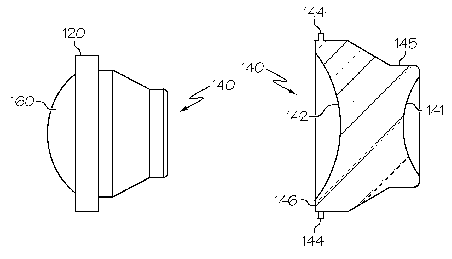
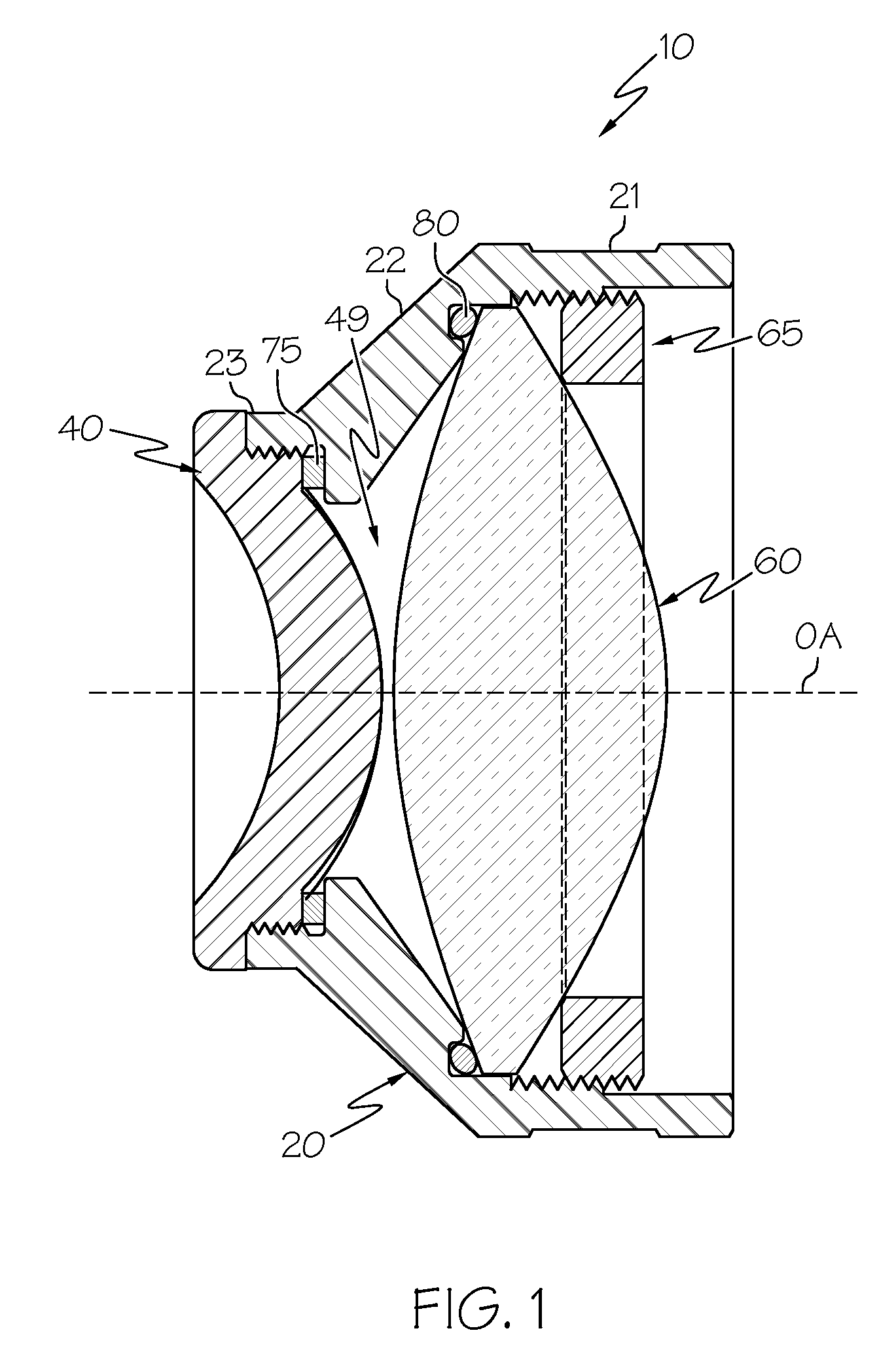
[0035]The present invention provides an ophthalmoscopy lens system, such as a lens system suitable for use during vitreoretinal surgery, which may be easily and effectively sterilized. In particular, lens systems according to the present invention may be sterilized (or disinfected) by immersion in chemical sterilants such as glutaraldehyde, hydrogen peroxide or bleach (e.g., sodium hypochlorite). These lens systems may also be sterilized by steam sterilization (such as by use of an autoclave). By proper selection of the materials used to manufacture the various components of the lens system, the lens system can be sterilized without significant damage to the components (particularly the individual lens elements) or degradation of the optical characteristics of the lens system. Some embodiments of the present invention are sealed such that the lens need not be disassembled for sterilization purposes, while other embodiments permit the lens to be quickly and easily disassembled prior ...


PUM


Abstract

An autoclavable and sterilent-resistant ophthalmoscopy lens system having a plastic contact lens, and at least one image forming lens element. An ophthalmoscopy lens system having a contact lens element, an image forming lens and a retaining ring is also provided.

Description

[0001]This application claims the benefit of U.S. Provisional Application Ser. Nos. 60 / 419,452 filed on Oct. 18, 2002 and 60 / 419,799 filed on Oct. 19, 2002, the entire disclosures of which are hereby incorporated herein by reference.BACKGROUND OF THE INVENTION[0002]1. Field of the Invention[0003]The present invention relates to ophthalmoscopy lens systems, particularly those which may be sterilized without component damage or optical degradation.[0004]2. Description of Related Art[0005]Various ophthalmoscopy lens systems have been developed for use in the diagnosis and treatment of the eye. Many of these lens systems, particularly indirect ophthalmoscopy lens systems which create a real aerial image of structures within the eye, include a contact lens element which is placed directly on a patient's cornea. One particular type of indirect ophthalmoscopy lens systems is that used for vitreoretinal surgery. Such lens systems are described, for example, in U.S. Pat. No. 5,963,301 (which...

Claims


Application Information

Patent Timeline
IPC IPC(8): A61B3/00
CPCA61B3/125A61F9/009G02B7/023G02B7/025G02B7/028
Inventor ROSS, III, DENWOOD F.EDWARDS, TIM D.MAREK, C. THOMAS
Owner VOLK OPTICAL
Why Eureka
Try Eureka