Optical measurement apparatus with laser light source

a measurement apparatus and laser light source technology, applied in the direction of optical radiation measurement, instruments, material analysis, etc., can solve the problems of poor signal-to-noise ratio, insufficient resolution bandwidth, poor performance etc., to achieve excellent coupling efficiency, improve the resolution of the measurement apparatus, and improve the effect of accuracy

Inactive Publication Date: 2007-07-17
RAYTHEON CANADA LTD
View PDF5 Cites 5 Cited by
  • Summary
  • Abstract
  • Description
  • Claims
  • Application Information

AI Technical Summary

Benefits of technology

[0013]The present optical measurement apparatus provides a high-intensity, narrowband laser light source with excellent coupling efficiency into the optical fibers. Resolution of the measurement apparatus is improved as compared with other types of light sources. The result is more accurate monitoring of the thin film thickness and improved wavelength resolution in the apparatus.

Problems solved by technology

However, variations in the deposition rate usually are present so that the thicknesses of the layers cannot be known with sufficient precision, just from the deposition parameters.
This apparatus is operable, but the present inventors have observed that it suffers from poor performance in its signal-to-noise ratio and an insufficient resolution bandwidth.
The result is that its performance is limited in its function of providing a real-time measurement of the thickness of the thin film being deposited.

Method used


Image

  • Optical measurement apparatus with laser light source
  • Optical measurement apparatus with laser light source
  • Optical measurement apparatus with laser light source

Examples


Embodiment Construction

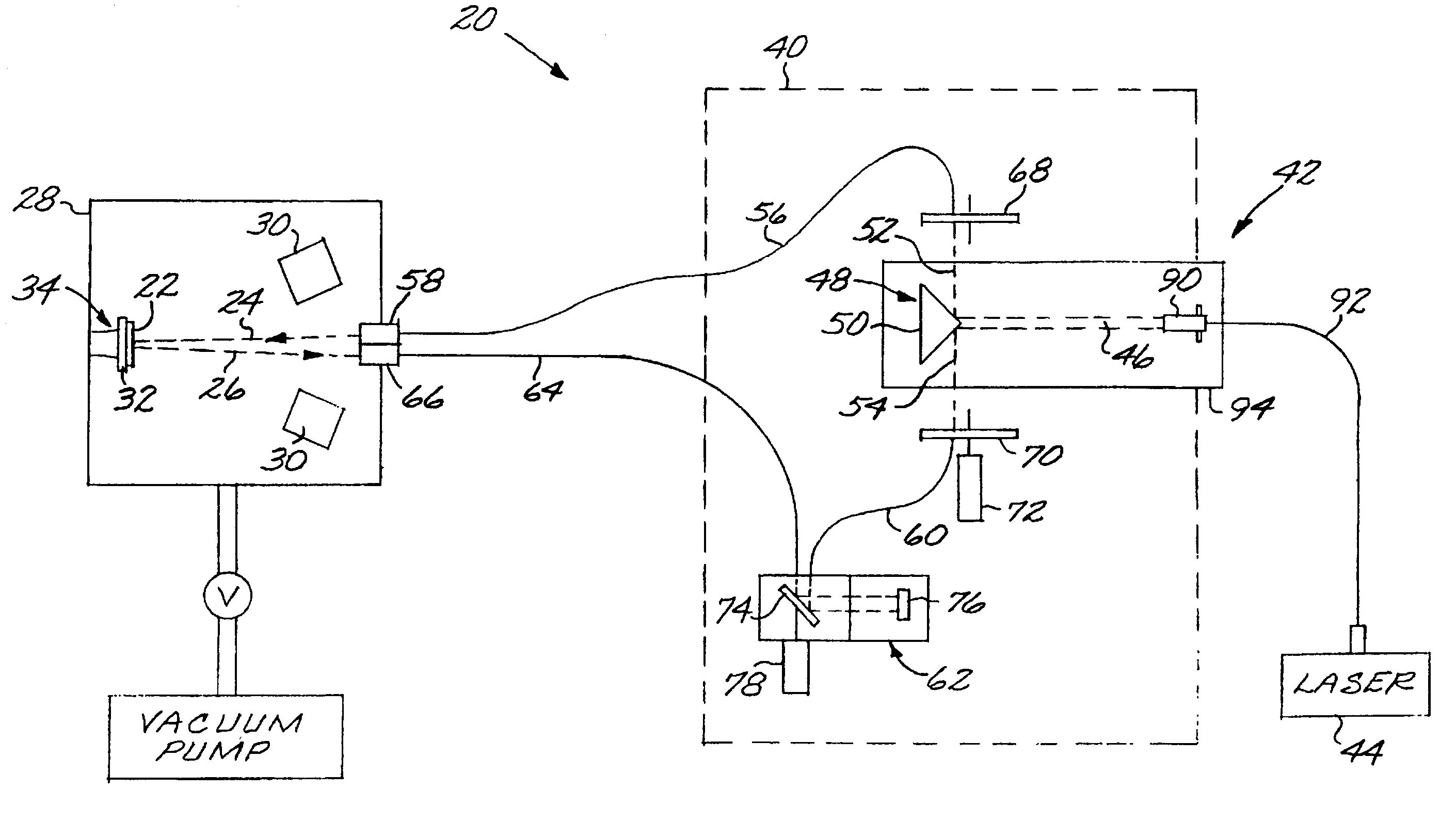
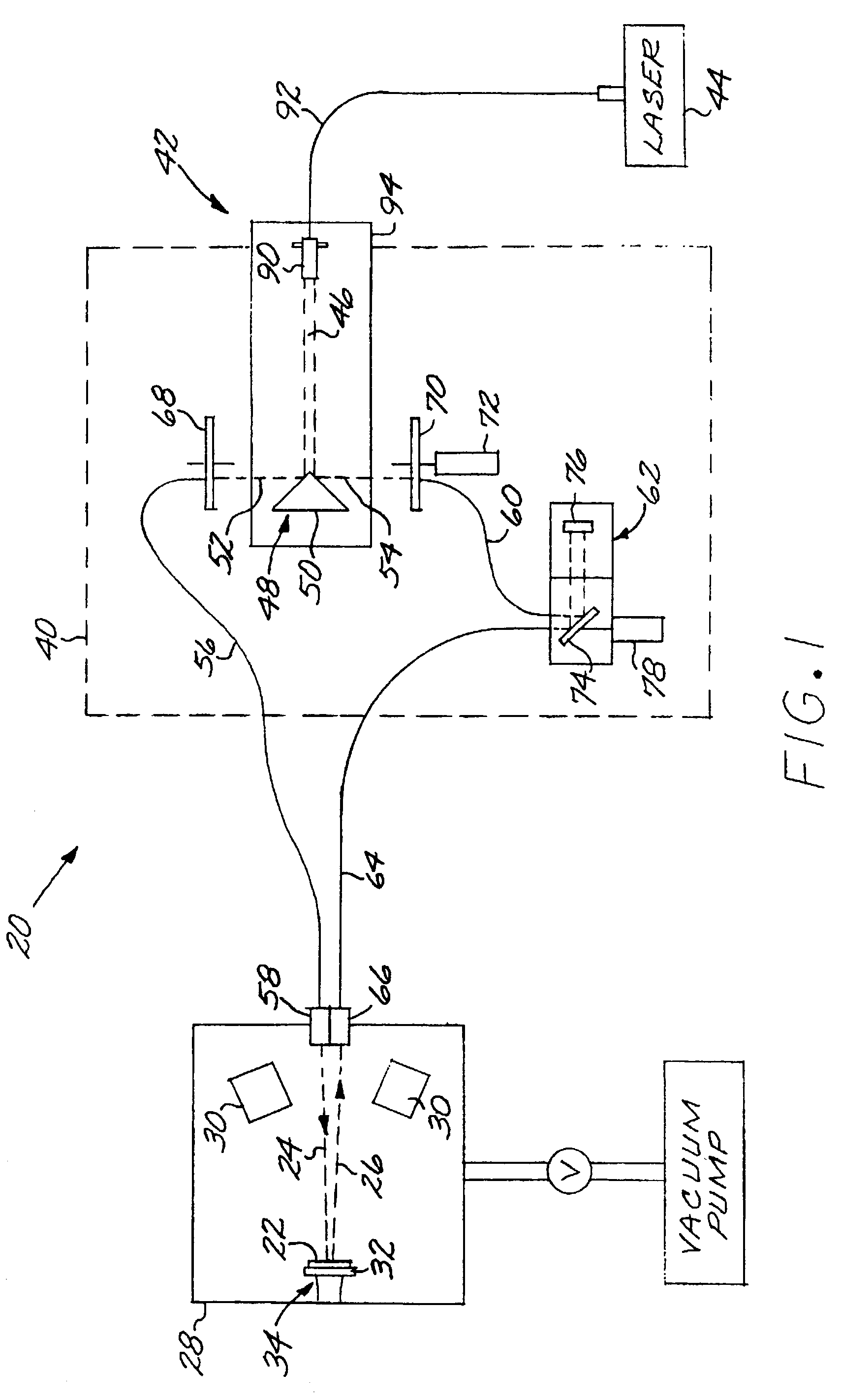
[0018]FIG. 1 depicts an optical measurement apparatus 20 operable with a test specimen 22, most preferably a thin-film test specimen. The optical measurement apparatus 20 optically measures physical characteristics of the test specimen 22, and therefore directs an incident light beam 24 onto the test specimen 22 and receives a reflected (as illustrated) or transmitted light measurement signal 26 from the test specimen 22. In a preferred application, the test specimen 22 is contained within a chamber 28, which is typically a vacuum chamber evacuated by a vacuum pump, but can also be a controlled-atmosphere chamber. In the illustrated case, the vacuum chamber 28 has deposition sources 30 therein to controllably deposit the test specimen 22 onto a substrate 32 supported from the wall of the vacuum chamber 28, thereby serving as a test specimen holder 34 for the optical measurement device 20. The test specimen 22 may have a single layer or, more commonly, a multilayer thin-film structur...


PUM

PropertyMeasurementUnit
diameteraaaaaaaaaa
wavelengthaaaaaaaaaa
thicknessaaaaaaaaaa

Abstract

An optical measurement apparatus operable with a test specimen has a light source with a laser having an output beam, and a beam splitter that splits the output beam of the laser into a first split beam and a second split beam. A test specimen holder holds the test specimen therein. A first optical fiber receives the first split beam and directs the first split beam against the test specimen in the test specimen holder. The apparatus further includes an instrumentation module. A second optical fiber receives the second split beam and conducts the second split beam to the instrumentation module. A third optical fiber receives signal light from the test specimen in the test specimen holder and conducts the signal light to the instrumentation module.

Description

[0001]This invention relates to optical measurement apparatus and, more particularly, to an optical measurement apparatus with a high intensity laser light source.BACKGROUND OF THE INVENTION[0002]Monolayer and multilayered thin films deposited on a substrate are used in a number of optical and other applications. The layers of such thin films are usually less than 1 micrometer, and sometimes much less than 1 micrometer, in thickness. They must be of precisely deposited thicknesses to be useful.[0003]The thin films are typically deposited by a vacuum deposition process such as electron beam deposition. A source of the deposited material and the target substrate are placed into a vacuum chamber, and the source is operated to deposit the required material to the required thickness. There are typically multiple sources as required for the multiple layers.[0004]The operation of the sources is calibrated so that the thickness of the deposited layers is reasonably well known. However, vari...

Claims


Application Information

Patent Timeline
Patent Type & Authority Patents(United States)
IPC IPC(8): G01J5/08G01B11/06G01N21/84
CPCG01B11/0616G01N21/8422
Inventor GABURA, ANDREW J.ROBITAILLE, BLAISE R.BALL, ROGER W.
Owner RAYTHEON CANADA LTD
Why Eureka
Try Eureka