Structure of AC type PDP

a display device and structure technology, applied in the direction of gas discharge vessels/containers, electrodes, gas-filled discharge tubes, etc., can solve the problems of high hygroscopic properties, long treatment time of one method, and the most difficult process, so as to reduce manufacturing costs, reduce process time, and reduce manufacturing costs.

Inactive Publication Date: 2007-07-17
TECHNOLOGY TRADE AND TRANSFER CORP
View PDF8 Cites 9 Cited by
  • Summary
  • Abstract
  • Description
  • Claims
  • Application Information

AI Technical Summary

Benefits of technology

[0012]According to the present invention, in order to solve the above-described problem, it is an object of the present invention to propose an AC type PDP electrode structure in which a metal or conductive material which can easily be formed is formed on a dielectric layer by an easier process such as a screen printing method without using an oxide dielectric cathode material such as MgO which is difficult to form and which has an electric charge accumulating function.
[0024]Further, also from a manufacturing standpoint, since the dielectric layer 3 and other layers can be formed by a thick film forming process such as a screen printing, the manufacturing facilities are inexpensive and the process time can be reduced considerably, which can decrease a manufacturing cost considerably.

Problems solved by technology

However, such oxide material is very unstable from a property standpoint and hence it is difficult to make.
Although it is customary to form such oxide material by a vacuum deposition method or a sputtering method, any one of methods needs a long treatment time because the whole of substrate is treated by a heating treatment within a vacuum apparatus which is highly evacuated.
Further, the manufacturing process has encountered with a serious problem in which MgO is high in hygroscopic property so that it is easily changed into Mg (OH)2, that is, magnesium hydroxide, its function as the cathode material being lost.
Hence, its process has been regarded as the most difficult process in the manufacturing process of PDP.

Method used


Image

  • Structure of AC type PDP
  • Structure of AC type PDP
  • Structure of AC type PDP

Examples


Embodiment Construction

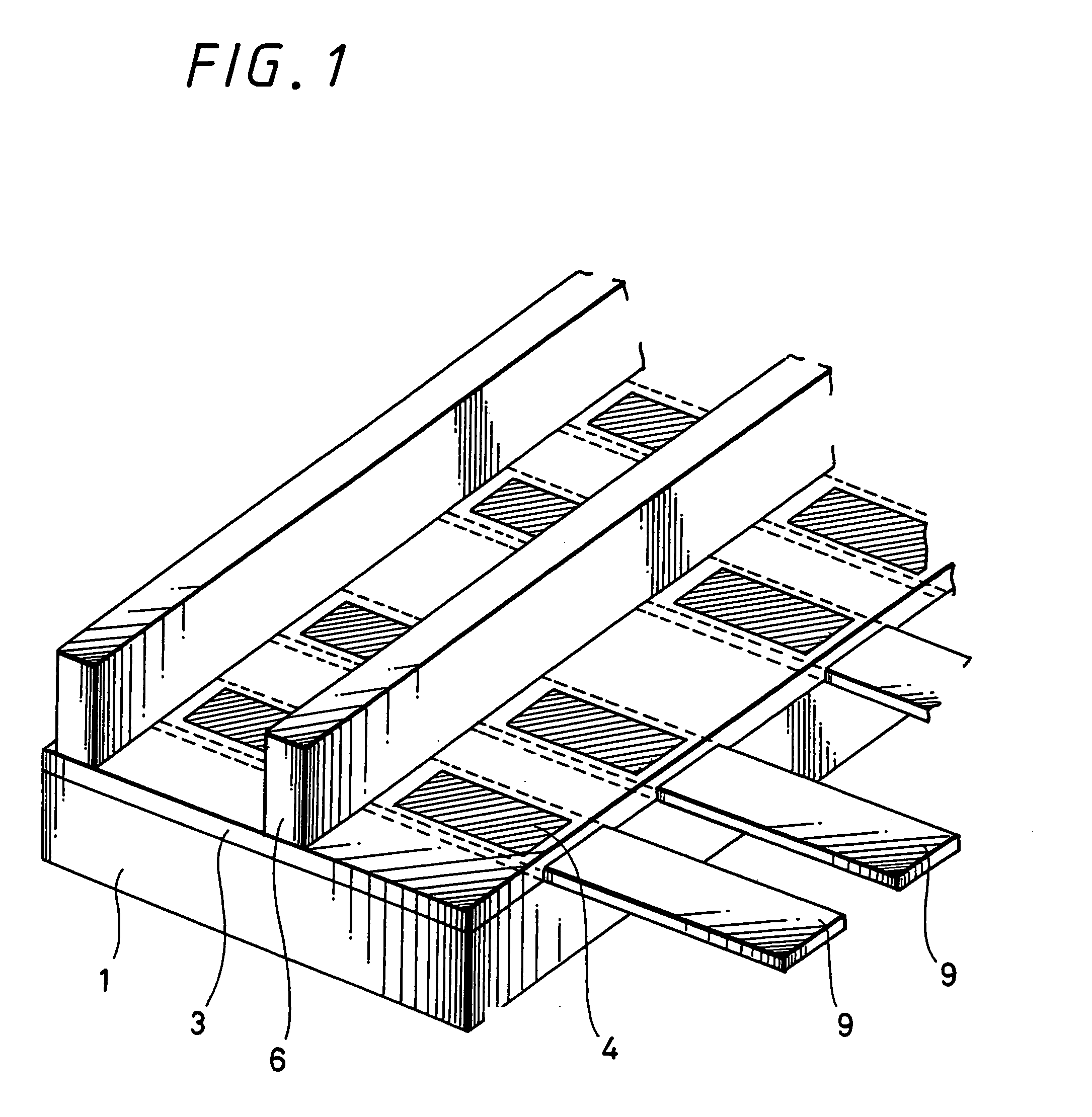
[0039]FIG. 1 is a development perspective view of a pixel portion which is used to explain an embodiment of the present invention.

[0040]In order to facilitate the understanding of the present invention, FIG. 1 shows an example of a rear surface plate of a PDP including a so-called transmission type fluorescent screen.

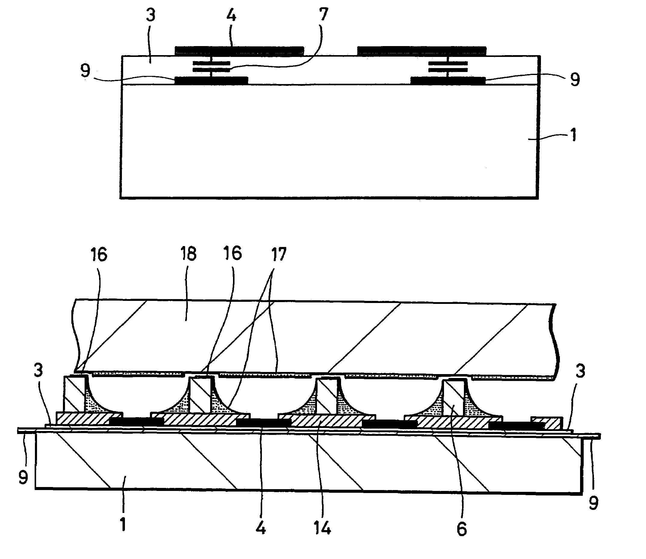
[0041]Although the following members are not shown in FIG. 1 because they are not directly related to the present invention, a front surface side substrate is opposed to a rear surface glass substrate 1 shown, a fluorescent substance is coated on the front surface side of the transmission type fluorescent screen and address electrodes are further disposed in an opposing fashion to a pair of electrodes 9 shown in FIG. 1.

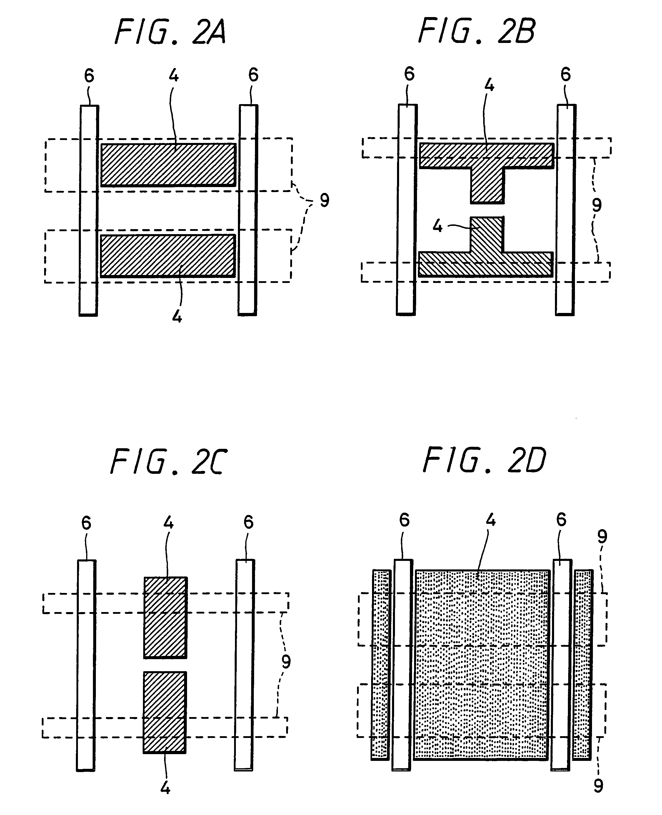
[0042]First, a pair of bus electrodes 9 for display discharge is formed on the rear surface glass substrate 1. The bus electrodes can easily be obtained by baking a conductive material such as a silver paste after such conductive material has been treated...


PUM

PropertyMeasurementUnit
thicknessaaaaaaaaaa
conductiveaaaaaaaaaa
electrostatic capacitanceaaaaaaaaaa

Abstract

Almost only choice by a secondary electron emission layer / protection layer covering the dielectric layer of an AC type PDP has been magnesium oxide (MgO) that is unstable during the production process and difficult to form, thus posing a serious production problem. An AC type PDP constructed such that, instead of covering the surface of a dielectric layer with a dielectric material such as MgO, an insular electrode is made by forming a conductive material such as nickel, aluminum, magnesium and lanthanum hexaboride into an insular shape, and the insular electrode is allowed to capacity-couple with a lower-layer bus electrode by means of an electrostatic capacity formed by a dielectric layer to operate the insular electrode as a sustained electrode.

Description

TECHNICAL FIELD[0001]The present invention relates to a structure of a display device to which gas discharge is applied, that is, a so-called PDP (plasma display panel).BACKGROUND ART[0002]A PDP (plasma display panel) is roughly classified into an AC type PDP and a DC type PDP from the characteristics of its electrode structure.[0003]As shown in FIG. 3B, the AC type PDP has a structure in which the surface of an electrode 2 is covered with a dielectric layer 3 in which an electrostatic capacitance 7 is formed, the surface of the dielectric layer being covered with a dielectric material 5 such as magnesium oxide with a high secondary electron radiation property. On the other hand, the DC type PDP is characterized by a structure in which the surface of an electrode is not covered with a dielectric layer but exposed to the discharge space to directly radiate secondary electrons from the surface of the electrode although not shown.[0004]Since the ordinary AC type PDP has a so-called ref...

Claims


Application Information

Patent Timeline
Patent Type & Authority Patents(United States)
IPC IPC(8): H01J17/49H01J11/40H01J11/12H01J11/14H01J11/16H01J11/22H01J11/24H01J11/26H01J11/30H01J11/32H01J11/34H01J11/36H01J11/38H01J11/42
CPCH01J11/14H01J11/24H01J11/38H01J11/28H01J2211/225H01J11/40
Inventor AMANO, YOSHIFUMI
Owner TECHNOLOGY TRADE AND TRANSFER CORP
Why Eureka
Try Eureka