Magnetic displacement ruler

a technology of measurement devices, which is applied in the direction of galvano-magnetic hall effect devices, instruments, and mechanical means, etc., can solve the problems of limiting the application range of such electronic digital display calipers, the structure disclosed in the above patents is complicated, and the caliper will work abnormally in wet environment or in the environmen

Inactive Publication Date: 2007-08-07
BEIJING AEROSPACE FENG GUANG ELECTRONICS TECHN CORP
View PDF13 Cites 64 Cited by
  • Summary
  • Abstract
  • Description
  • Claims
  • Application Information

AI Technical Summary

Benefits of technology

[0004]An object of the invention is to provide a magnetic displacement measurement device, which not only can normally work in the wet and oil polluted environment, but also have the advantages of simple structure, convenient manufacture, low price, low power consumption and high precision.

Problems solved by technology

The caliper will work abnormally in wet environment or in the environment with lubrication and dust and the like.
However, it is difficult to avoid such environment in practice, which will limit the application range of such kind of electronic digital display caliper.
However, the structure disclosed in the above patents is complicated and has high power consumption and low precision, which is not usable as a portable measuring tool.
Because it is not easy to make the magnetization intensity of the main ruler 142 is in the form of single layer film, the resistance change rate is small, which would impose high requirement on the measurement circuit.
Therefore, this method will bring displacement float due to external electronic interference and environment variation, eventually will influence the measurement precision.

Method used


Image

  • Magnetic displacement ruler
  • Magnetic displacement ruler
  • Magnetic displacement ruler

Examples


first embodiment

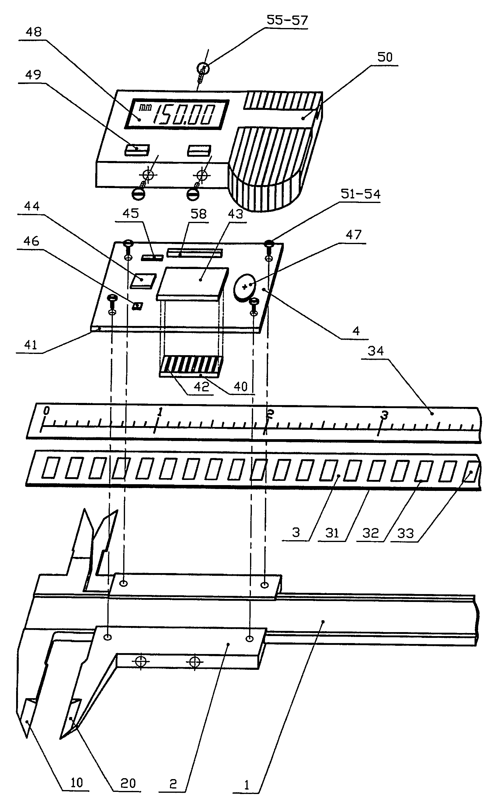
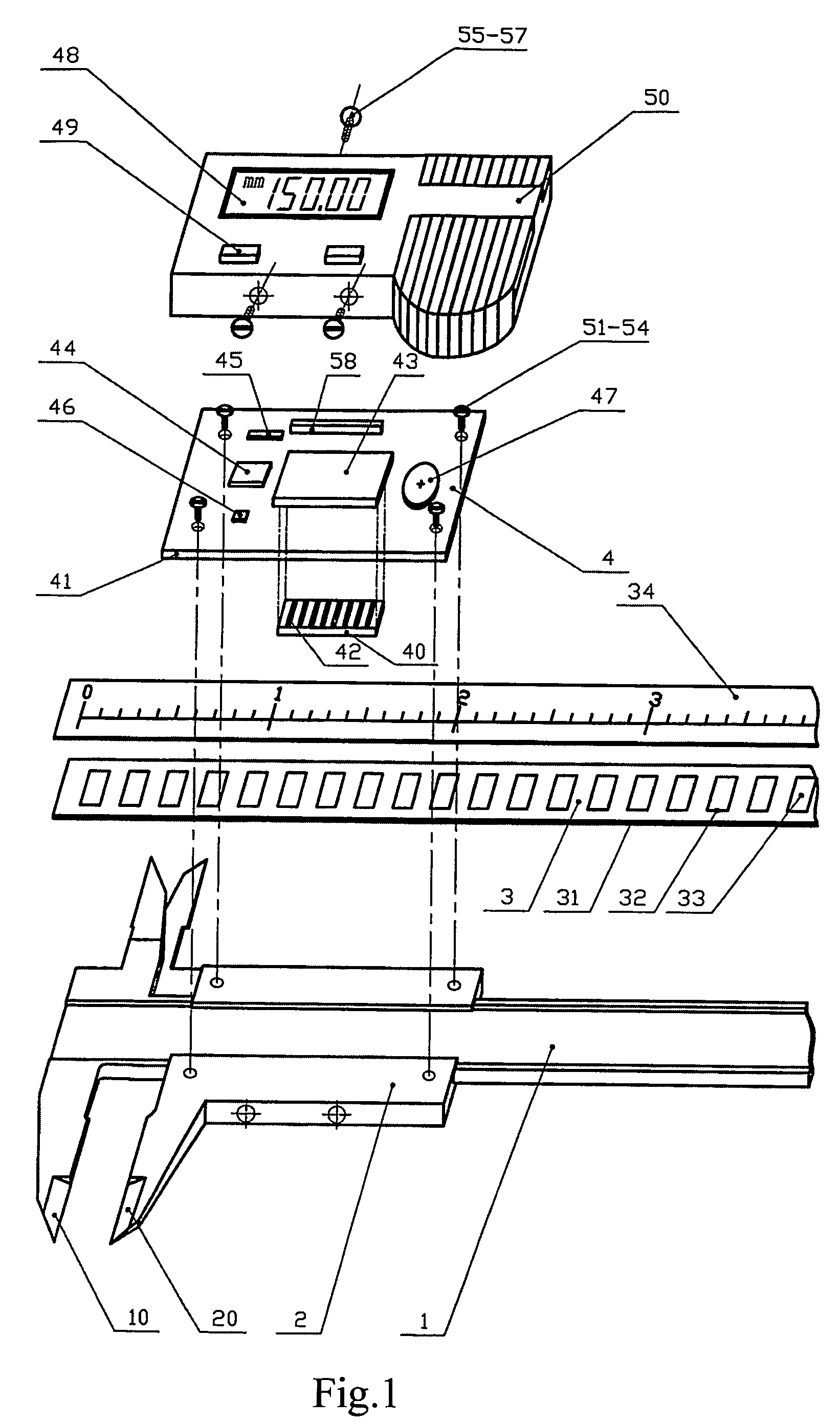
[0043]FIG. 4 shows the main ruler 3. The main ruler 3 are manufactured by the following steps: using non-magnetic printed circuit board (PCB) as a substrate 31; making a mother plate according to the desired grid shape and size; copying the pattern onto a copper foil 32 which has a photosensitive film; then making the copper foil 32 be desired girds with the grid pitch of λ and the width of 0.1-0.5λ by chemical corrosion; finally coating the magnetic material of Nickel onto the surface of the grids by electroplating or chemical plating so as to form the magnetic film 33. the above manufacture method has the advantages of high precision, advanced processing technique, low cost and thin thickness of the main ruler 3, and is well suitable for mass production, especially for producing portable measuring tools. In addition, glass and ceramic may be used as substrate and the magnetic material may be coated onto the substrate according to the pattern of the grids by vacuum plating and etch...

second embodiment

[0044]FIG. 5 shows the main ruler 3. The main ruler 3 is manufactured by the following steps: using non-magnetic material as the substrate 31; making magnetic material be the grids 33 according to the desired grid shape and size by mechanical process, such as punching, milling, linear cutting, etc.; then integrating the grids 33 and the substrate 31 to form the main ruler 3.

third embodiment

[0045]FIG. 6 shows the main ruler 3. The main ruler 3 is manufactured by directly machining the magnetic material into the grids 33. This manufacturing method imposes a higher requirement on the mechanical process.

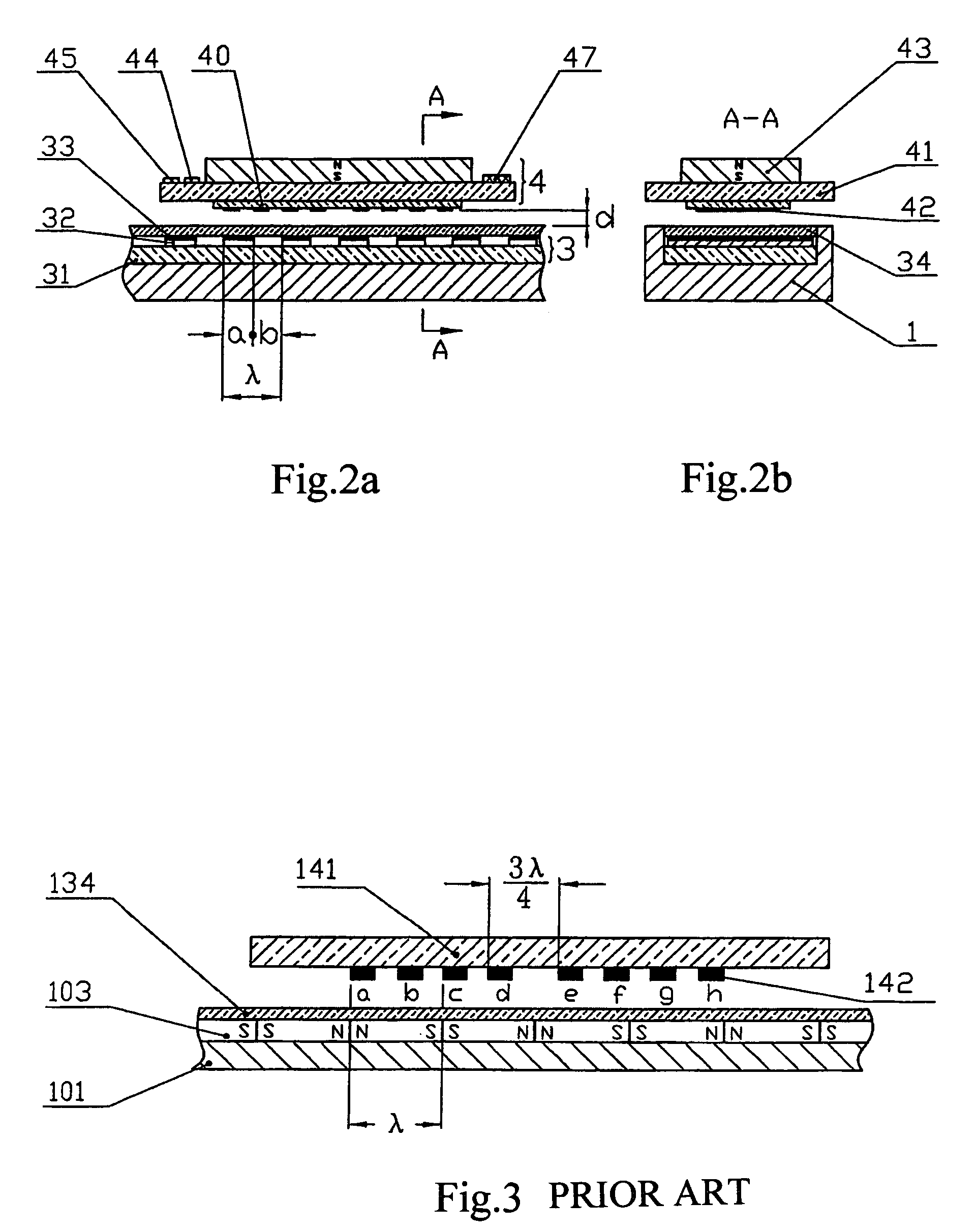
[0046]FIG. 7a shows the first embodiment of the distribution of the magnetoresistances. Two most basic measurement bridges composed of eight magnetoresistances 42a˜42h are shown in the Figure. In practice, in order to reduce the power consumption, these resistors are connected in series, as shown in FIG. 8 and FIG. 9. The magnetoresistances 42a˜42d constitutes the bridge S and the magnetoresistances 42e˜42h constitute the bridge C; and the position difference between the bridge S and the bridge C is nλ / 4, wherein n=1, 3, 5, 7 . . . , so that the measurement circuit may judge the movement direction of the vernier 2. The magnetoresistances in each bridge are arranged at intervals of λ / 2, as shown in FIG. 7, and are connected sequentially to form the bridge as shown in FIG. 1...


PUM


Abstract

This invention relates to a magnetic displacement measurement device, which comprises a ruler body and a vernier, wherein a magnetic main ruler is fixed on the ruler body, and a secondary ruler is fixed on the vernier; the secondary ruler comprises a magnetic sensor and a measurement circuit thereon; said magnetic sensor is composed of magnetoresistances; said measurement circuit comprises at least two measurement bridges composed of magnetoresistances; the movement distance of the vernier is displayed on the display screen of the device after being detected by the magnetic sensor and being processed by the measurement circuit. The magnetic displacement measurement device provided by the invention not only can normally work in the wet and oil polluted environment, but also has the advantages of simple structure, convenient manufacture, low price, low power consumption and high precision.

Description

TECHNICAL FIELD[0001]The invention relates to a magnetic measurement device for measuring length and angle, particularly to a magnetic measurement device of an electronic digital display caliper.BACKGROUND OF THE ART[0002]Conventional mechanical vernier caliper is gradually replaced with the electronic digital display caliper. The electronic digital display caliper most widely used at present uses capacitive displacement sensors, and the output of the sensor is associated with the relative positions of the capacitor plates on the main ruler and the secondary ruler. With the processing of the electronic circuit, the data of the relative positions is displayed in the display screen. The electronic digital display caliper in this principle is described in SE7714010 and European Patent EP0053091. Although the electronic digital display caliper in this principle has high precision and low power consumption, there is a specific requirement for application environment of the caliper. The c...

Claims


Application Information

Patent Timeline
Patent Type & Authority Patents(United States)
IPC IPC(8): G01B7/14G01B3/20G01B7/02G01D5/14G01D5/245
CPCG01B3/205G01D5/145G01D5/2451
Inventor MA, LIYAOCHEN, YINGHUAJIANG, YINGCHUNZHANG, JIE
Owner BEIJING AEROSPACE FENG GUANG ELECTRONICS TECHN CORP
Why Eureka
Try Eureka