Vehicle auxiliary power unit, assembly, and related methods

a technology for auxiliary power units and vehicles, applied in the direction of electric generator control, machines/engines, electric devices, etc., to achieve the effect of preventing excessive vehicle battery depletion, selective disassembly, and avoiding overloading of auxiliary engines

Inactive Publication Date: 2007-08-21
LONGHORN SCSF LTD +1
View PDF44 Cites 78 Cited by
  • Summary
  • Abstract
  • Description
  • Claims
  • Application Information

AI Technical Summary

Benefits of technology

[0013]Advantageously, in the preferred embodiment of the present invention, the voltage regulator can selectively disable power to at least one of the electrical components in the event of low vehicle battery voltage, when so existing, to thereby prevent excessive battery depletion. This prevents the driver having to succumb to a “no-start” situation where the driver inadvertently depletes the vehicle batteries to a point where there is insufficient power to restart the vehicle. The vehicle engine includes a block heater electrically preferably connected to the vehicle battery, the auxiliary alternator, and the voltage regulator. In the preferred embodiment of the present invention, the voltage regulator is adapted to selectively disable power to the block heater and / or the inverter in the event of low vehicle battery voltage, when so existing, to thereby prevent excessive battery depletion. This allows the alternator to charge the battery while still providing either heating or cooling to the sleeper. The monitoring and disabling function can be accomplished according to a duty cycle to, among other things, prevent any erroneous effect due to momentary voltage fluctuations. The voltage regulator also can sense engine speed “RPM” during start-up to allow engine speed to obtain a minimum preselected speed prior to enabling the auxiliary alternator to supply power. Further, the voltage regulator can limit maximum available current from the auxiliary alternator when the auxiliary compressor is engaged to avoid overloading the auxiliary engine and can disengage the alternator from supplying power in the event the engine speed decreases below a preselected speed.
[0015]Embodiments of the present invention also include a method of power regulation of an auxiliary power unit assembly to operate an auxiliary air conditioning and heating system. For example, in an embodiment of the present invention the method includes operating the auxiliary engine while the main engine is off, thereby generating DC voltage with the auxiliary alternator, applying a charging voltage from the auxiliary alternator to the main battery, converting some of the DC voltage to AC voltage and powering an AC electrical component, and ceasing to power the AC electrical component if the main battery voltage drops below a selected minimum. Its regulator senses the engine speed (RPM) of an auxiliary engine during start-up to allow engine speed to obtain a minimum selected speed prior to enabling an auxiliary alternator to drive an electrical load until after the auxiliary engine obtains the minimum selected speed, determining whether an auxiliary compressor is being driven by the auxiliary engine, and responsive to such determination, limiting maximum available current from the auxiliary alternator to power the various electrical components when the auxiliary compressor is engaged, to avoid overloading the auxiliary engine. The method can also include selectively disabling power to the block heater and optionally the inverter in the event of low vehicle battery voltage to prevent excessive vehicle battery depletion, and to provide a maximum voltage to the battery to recharge the battery when simultaneously providing heating or cooling, as desired, to a vehicle personnel compartment.

Problems solved by technology

Further, the voltage regulator can limit maximum available current from the auxiliary alternator when the auxiliary compressor is engaged to avoid overloading the auxiliary engine and can disengage the alternator from supplying power in the event the engine speed decreases below a preselected speed.

Method used


Image

  • Vehicle auxiliary power unit, assembly, and related methods
  • Vehicle auxiliary power unit, assembly, and related methods
  • Vehicle auxiliary power unit, assembly, and related methods

Examples


Embodiment Construction

[0020]The present invention will now be described more fully hereinafter with reference to the accompanying drawings which illustrate embodiments of the invention. This invention may, however, be embodied in many different forms and should not be construed as limited to the illustrated embodiments set forth herein. Rather, these embodiments are provided so that this disclosure will be thorough and complete, and will fully convey the scope of the invention to those skilled in the art. Like numbers refer to like elements throughout, and the prime notation, if used, indicates similar elements in alternative embodiments.

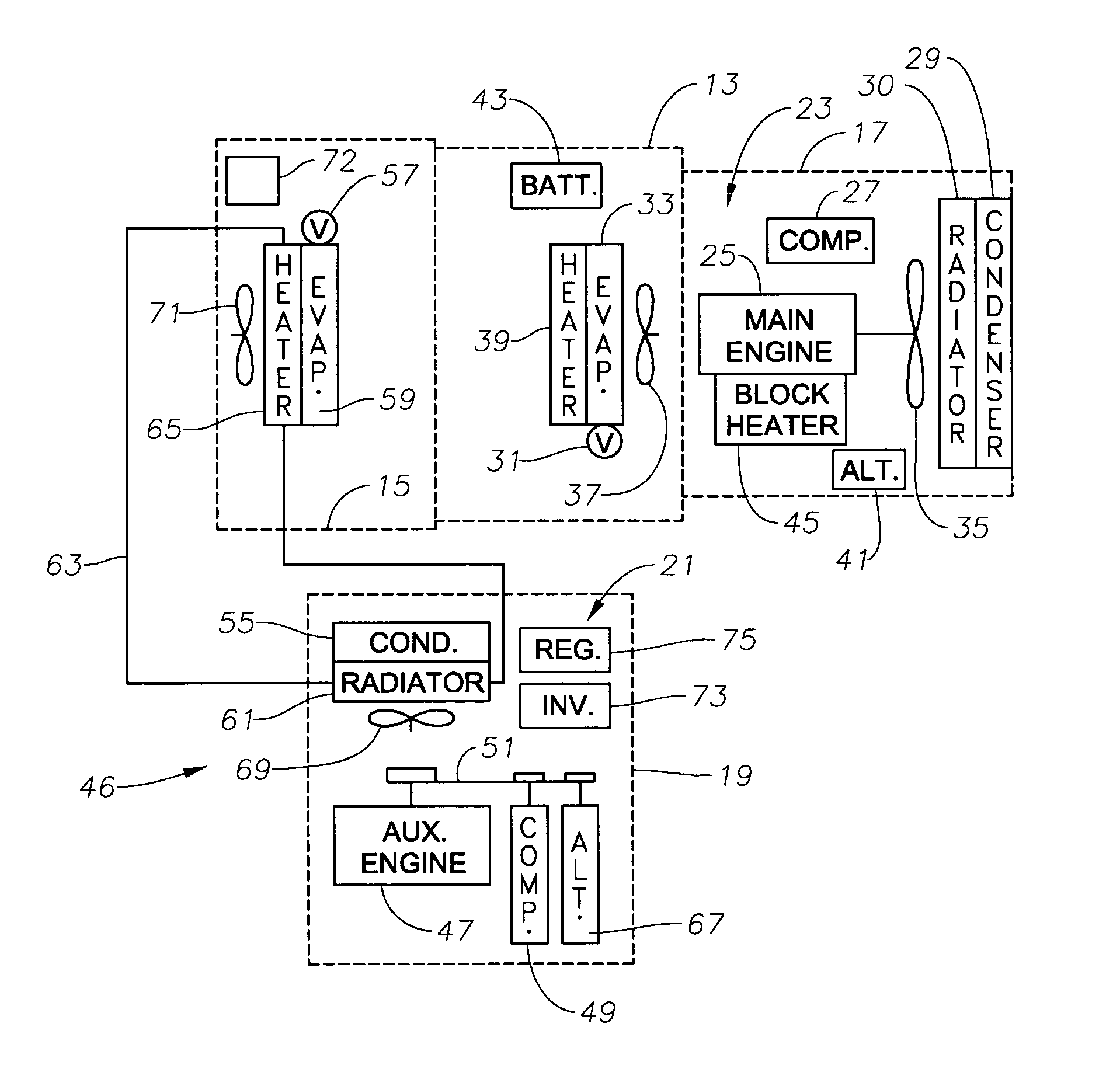
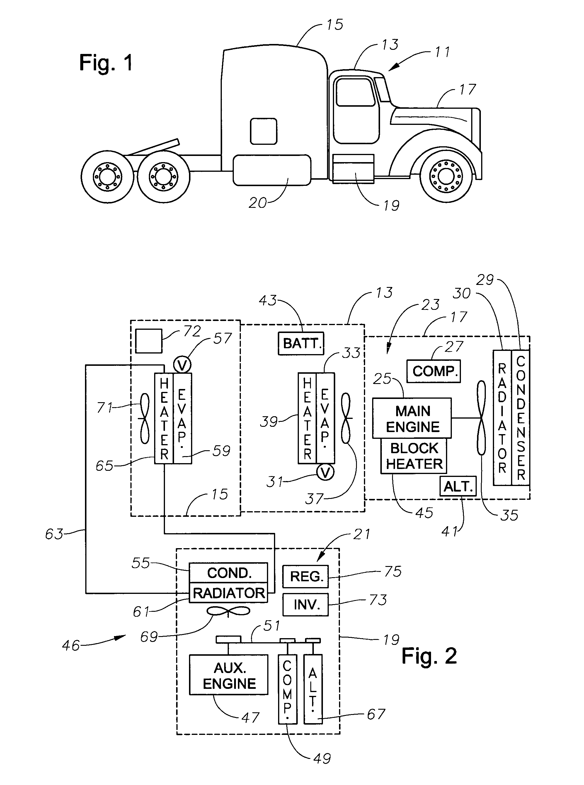
[0021]FIG. 1 illustrates a truck tractor 11 that has a forward passenger compartment or cab 13 and a rear sleeping and resting compartment 15. The driver is situated in cab 13 while driving truck 11, and uses the rear passenger compartment 15 for storage, a living area, entertainment center, and sleeping at other times. Truck tractor 11 has an engine compartment 17 in fr...


PUM


Abstract

A truck includes an auxiliary power unit having components specifically selected such that they form a stand-alone unit that can fit within an auxiliary compartment of a vehicle and deliver heating, cooling, and additional electric power to the vehicle. Included is an auxiliary engine, an auxiliary alternator, and an auxiliary condenser to provide coolant for a personnel compartment mounted evaporator. An auxiliary voltage regulator provides a ramp-up feature to minimize excessive start-up loads, limits maximum available current from the auxiliary alternator when the auxiliary compressor is engaged, and selectively disables power to electrical components in the event of low vehicle battery voltage. The auxiliary engine includes a radiator system to provide heated fluid for a personnel compartment mounted heat exchanger.

Description

RELATED APPLICATIONS[0001]This application is related to and claims priority from provisional application Ser. No. 60 / 491,401, filed Jul. 31, 2003, titled “Voltage Regulator for Auxiliary Power Unit.”BACKGROUND OF THE INVENTION[0002]1. Field of the Invention[0003]The present invention relates generally to auxiliary power systems for vehicles, more specifically to power regulation of an auxiliary power unit to operate the auxiliary air conditioning and heating system.[0004]2. Description of the Related Art[0005]Many vehicles in particular truck tractors typically referred to as semi-tractor-trailers are equipped with sleeping and resting compartments. These compartments are provided to save driver the time and expense of procuring local sleeping arrangements during extended down-time and to allow the driver to provide personal security to the vehicle, along with other incidental benefits.[0006]A problem faced by the drivers of these vehicles is that during very warm weather and very ...

Claims


Application Information

Patent Timeline
Patent Type & Authority Patents(United States)
IPC IPC(8): F02D29/06B60H1/00B60H3/00B61D27/00H02P9/04B60H1/32B60L3/00F02B63/04F02B63/06
CPCB60H1/3226B60H1/3232F02B63/04F02B63/06
Inventor BRUMMETT, KEIVPANNELL, BOBBY L.SHIELDS, NEAL G.
Owner LONGHORN SCSF LTD
Why Eureka
Try Eureka