
Ethernet switching apparatus and method using frame multiplexing and demultiplexing

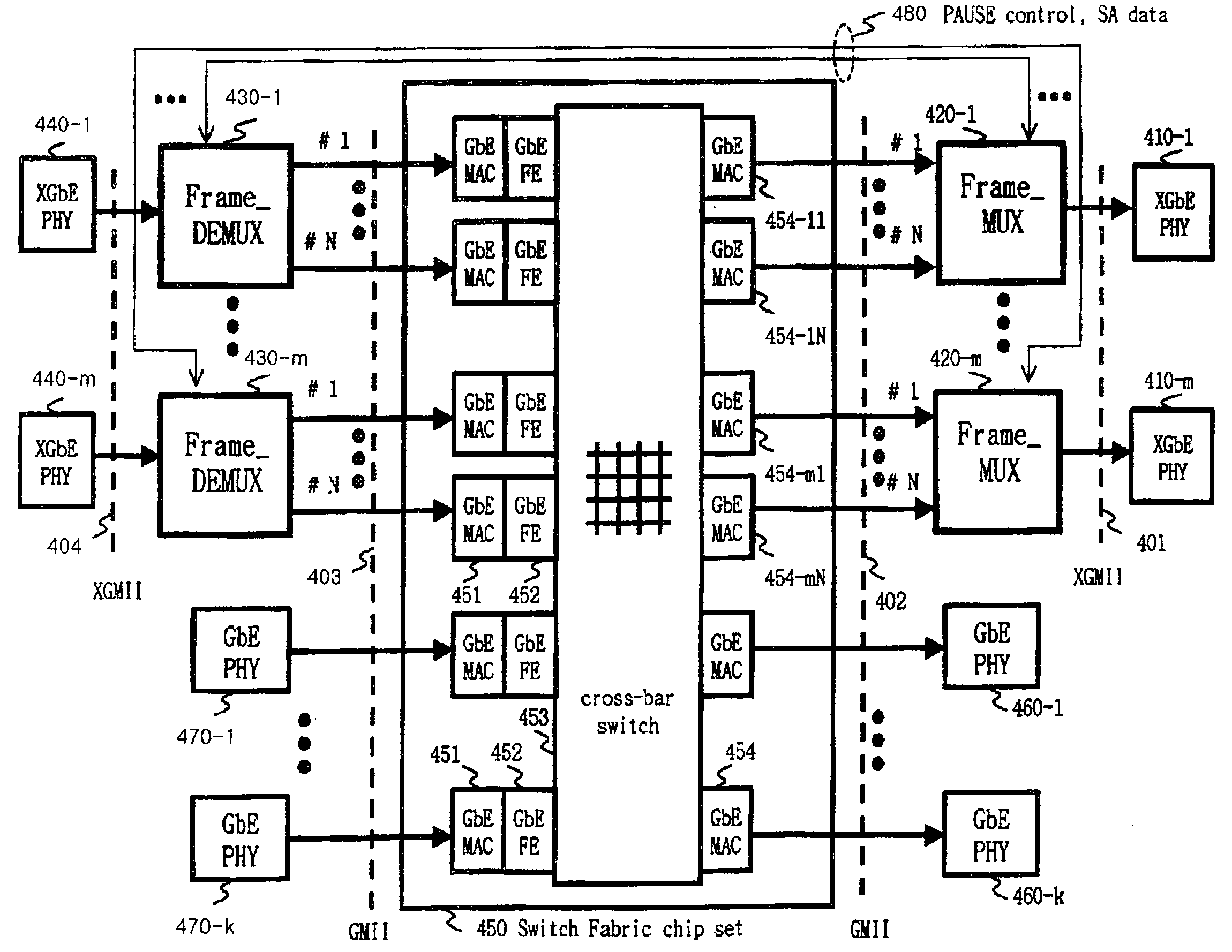
a technology of ethernet switching and frame multiplexing, applied in the field of ethernet switching apparatus and method, can solve the problems of reducing the efficiency of bandwidth use, scalability of network switches, and the limitation of the maximum processing speed per user port to those of ethernet ports of unit switch modules, so as to widen the range of applicable chip sets

Inactive Publication Date: 2007-08-21
ELECTRONICS & TELECOMM RES INST
View PDF7 Cites 38 Cited by
  • Summary
  • Abstract
  • Description
  • Claims
  • Application Information

AI Technical Summary

Benefits of technology

[0012]The present invention provides an Ethernet switching apparatus and method using frame multiplexing and demultiplexing, which uses a universal gigabit switch chip set and applies standard interfaces to a multiplexer and a demultiplexer, thus reducing the costs caused by the use of universal chips, and which performs packet multiplexing, thus maximizing the efficiency of channels.
[0016]Through the implementation, an Ethernet switch having a plurality of 10 gigabit Ethernet ports can be realized by using a universal gigabit Ethernet switch fabric chip set with a GMII interface, multiplexing gigabit Ethernet frames to 10 gigabit Ethernet frames, and demultiplexing 10 gigabit Ethernet frames to gigabit Ethernet frames. Therefore, the present invention uses a low speed switch chip set, without using a coprocessor with a high speed frame processing function, thus realizing economic benefits. Further, the present invention can use conventional universal chips by applying standard interfaces to input and output interface manners, and can widen a range of applicable chip sets by ensuring a frame transmission sequence without information on the internal path of the used switch chip set, thus enabling a user to freely select chip sets without depending on a specific chip set provider when the Ethernet switch is designed.
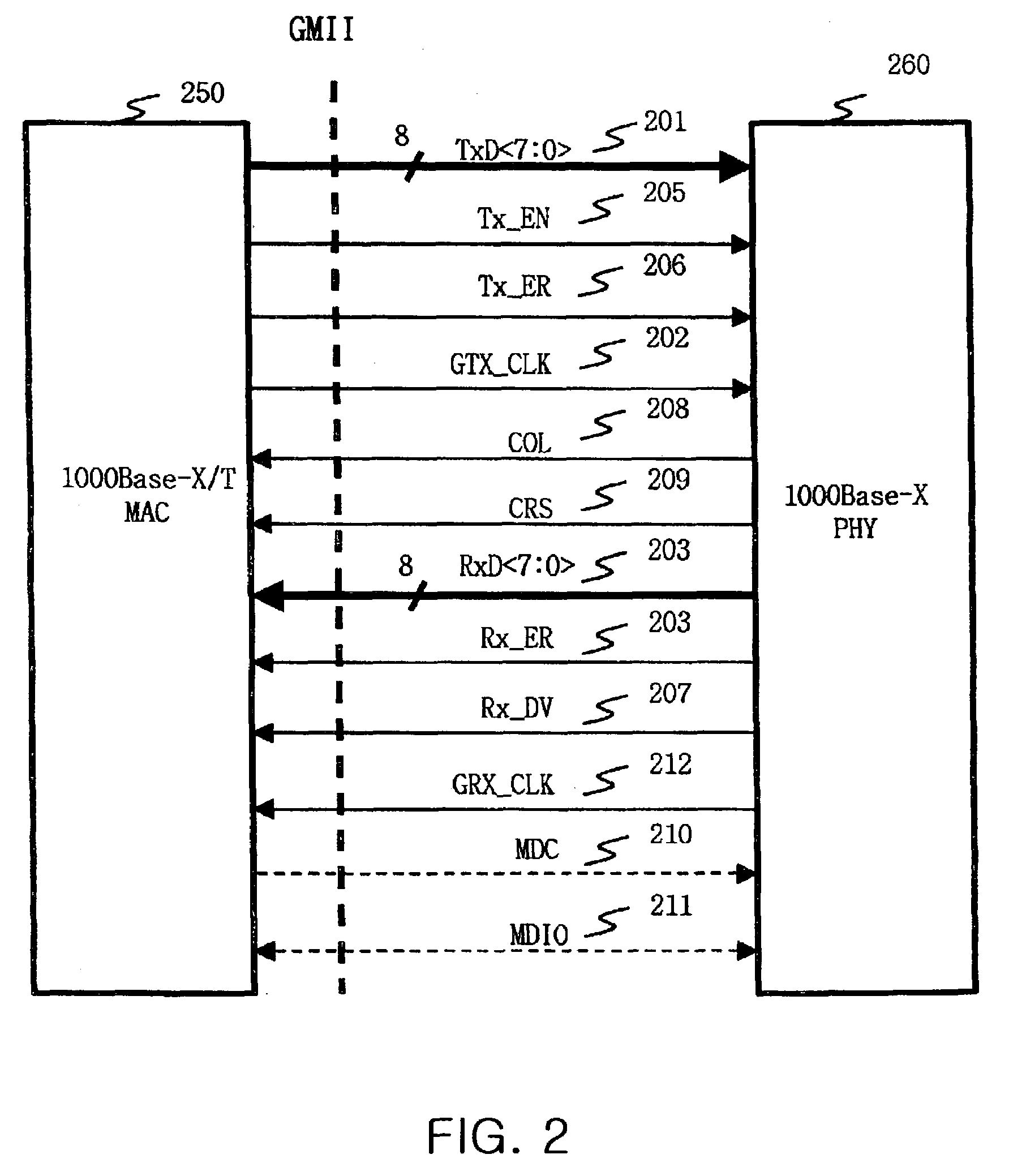
[0017]In the present invention, GMII and XGMII, which are IEEE 802.3 standard interfaces, are used between a gigabit Ethernet Media Access Control (MAC) unit and a 10 gigabit Ethernet transceiver. Therefore, the Ethernet switching apparatus having a plurality of 10 gigabit Ethernet ports can be implemented using a universal switch chip set, for example, SwitchCore CXE-16 and CXE-2010, Intel IXE5416, IBM PRS64G, Marvell GT-4830xA (Marvel Prestera-EX120), GT-48360, IBM NP4GS3, etc., and a physical layer chip. Further, the present invention is advantageous in that it can transmit Ethernet frames by multiplexing and demultiplexing the Ethernet frames without varying transmission protocols. Further, the present invention is advantageous in that, even if switch path information within a gigabit Ethernet switch chip set is not known, frame transmission sequence, which is one of basic principles of an Ethernet switch, does not change. Especially, the present invention is characterized in that it can dynamically multiplex packets to generate 10 gigabit Ethernet frames and can transmit the generated 10 gigabit Ethernet frames, without using expensive and complicated functional units, such as coprocessors for packet classification and traffic management. Moreover, the present invention is advantageous in that it can multiplex ten or more gigabit Ethernet ports when gigabit Ethernet frames are transmitted.

Problems solved by technology

However, time division multiplexing (TDM) is disadvantageous in that frames must be configured to recognize respective input ports, and exclusive channels must be used due to the characteristics of TDM, thus decreasing the efficiency of bandwidth use.
However, in the above method, the scalability of the network switch is very high, while a maximum processing speed per port obtained by a user port is limited to those of Ethernet ports of the unit switch modules.
Moreover, this method is problematic in that the bus-shaped unit switch modules must have a processing capacity equal to or greater than 10 gigabits so as to provide 10 gigabit Ethernet ports to users.
However, the switch having the above architecture is problematic in that its maximum capacity and bandwidth are fundamentally limited due to the transmission speed of the fiber optic link.
This method is advantageous in that it can reduce the number of ATM cell converters and the Ethernet frame converters, while it is disadvantageous in that, since it uses the crossbar switch twice, packet converting ability per unit time of the crossbar switch is decreased as the frequency of packet transmission between the ATM port and the Ethernet port is increased.
However, the switching fabric using the protocol method is limited in that the entire capacity of the switching fabric is determined according to the transmission speed of the ring which is a part constituting the core of the switching fabric, and is problematic in that it causes a burden of frame conversion due to the use of an exclusive device.
As described above, the conventional TDM method is problematic in that the efficiency of bandwidth use is decreased, and the switching fabric employing a ring architecture is problematic in that the transmission speed of the ring must be increased to be greater than 10 Gbps.
Further, the network switch using a crossbar switch is problematic in that the processing speed of the crossbar switch is inevitably reduced to the maximum speed obtained by a port.
The switching fabric using an exclusive device or an exclusive protocol for traffic management is problematic in that it requires an additional high speed switch, and a protocol converter for reconverting converted high speed packets into original Ethernet packets, and further requires an additional interface circuit for connection to a conventional chip set.

Method used


Image

  • Ethernet switching apparatus and method using frame multiplexing and demultiplexing
  • Ethernet switching apparatus and method using frame multiplexing and demultiplexing
  • Ethernet switching apparatus and method using frame multiplexing and demultiplexing

Examples


Embodiment Construction

[0030]Hereinafter, embodiments of the present invention will be described in detail with reference to the attached drawings.

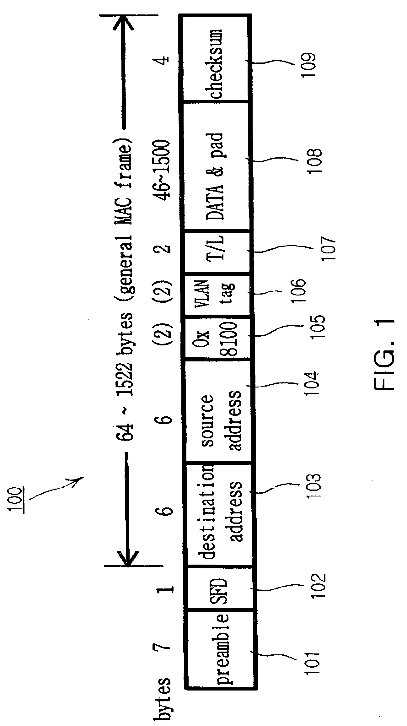
[0031]FIG. 1 is a view showing the format of an Ethernet frame applied to the present invention, wherein the format of a frame applied to the Ethernet having typical MAC frames is depicted. Referring to FIG. 1, the construction and operation of an Ethernet frame 100 is described in detail on the basis of standards defined in IEEE 802.3.

[0032]That is, if “10101011” which is a Start of Frame Delimiter (SFD) 102 appears after a 7-byte preamble 101 of identical “10101010” patterns, the SFD 102 is recognized to indicate the start of a MAC frame. After the SFD 102, a 6-byte destination address (DA) 103 and a 6-byte source address (SA) 104 follow in order. If the Ethernet frame is applied to a Virtual Local Area Network (VLAN), a 2-byte Ox8100 value 105 for representing that its next two bytes represent a VLAN tag, and a 2-byte VLAN tag 106 corresponding to the Ox8100...


PUM


Abstract

The present invention provides an Ethernet switching apparatus using frame multiplexing and demultiplexing. The Ethernet switching apparatus has a plurality of frame demultiplexers, a plurality of frame multiplexers and a switch fabric chip set. The frame demultiplexers convert at least one 10 gigabits Ethernet frame into a plurality of gigabit Ethernet frames. The frame multiplexers convert a plurality of gigabit Ethernet frames into at least one 10 gigabits Ethernet frame. The switch fabric chip set is provided with input and output interfaces using the GMII, and is connected to the frame demultiplexers and the frame multiplexers in the GMII format. The switch fabric chip set outputs frames through an arbitrary usable one of a plurality of GMII ports connected to a corresponding frame multiplexer if the frames are transmitted to the corresponding frame multiplexer.

Description

BACKGROUND OF THE INVENTION[0001]1. Field of the Invention[0002]The present invention relates generally to an Ethernet switching apparatus and method, and more particularly to an Ethernet switching apparatus and method using frame multiplexing and demultiplexing, which can correctly set a frame transmission sequence without information on the internal path of a switch fabric chip set by multiplexing a plurality of 1 gigabit Ethernet frames to one or more 10 gigabit Ethernet frames and demultiplexing one or more 10 gigabit Ethernet frames to a plurality of 1 gigabit Ethernet frames.[0003]2. Description of the Prior Art[0004]Generally, in order to implement an Ethernet switching apparatus, the configuration of a shared bus is used if a frame transmission speed of an input / output port is not high and a memory speed is low. On the other hand, an Ethernet switching apparatus is implemented using a switch fabric employing a crosspoint matrix so as to solve a bandwidth problem of the share...

Claims


Application Information

Patent Timeline
IPC IPC(8): H04J3/04H04L12/56
CPCH04L49/352H04L49/25H04L49/3009H04L49/3018H04L49/3027H04L2012/5603
Inventor KANG, SUNG SOOJUNG, HAE WONLEE, HYEONG HO
Owner ELECTRONICS & TELECOMM RES INST
Learn More