Semiconductor device with single crystal semiconductor layer(s) bonded to insulating surface of substrate

a technology of semiconductor layer and substrate, applied in mechanical devices, transportation and packaging, gearing, etc., can solve the problems of limiting the performance improvement of polysilicon tft, difficult to integrate controllers, da converters and other functional circuits, and difficult in practice to achieve the effect of reducing the level differen

Active Publication Date: 2007-08-28
SHARP KK
View PDF10 Cites 28 Cited by
  • Summary
  • Abstract
  • Description
  • Claims
  • Application Information

AI Technical Summary

Benefits of technology

[0026]In order to overcome the problems described above, an object of the present invention is to reduce the level difference to be created on the surface of a substrate when a single crystal semiconductor layer is bonded onto the substrate.
[0042]In yet another preferred embodiment, the method may further include, after the step (e), the step of (f) selectively etching, and reducing the thicknesses of, the second insulating layer and the single crystal semiconductor layer, thereby substantially equalizing the thickness of the second insulating layer with that of the first insulating layer.
[0054]According to various preferred embodiments of the present invention described above, the level difference to be created on the surface of a substrate by bonding a single crystal semiconductor layer thereto can be reduced significantly as compared with a conventional one. In addition, a high-reliability electronic device, including a single crystal semiconductor device and a non-single crystal semiconductor device on the same substrate, can be provided. By integrating the single crystal and non-single crystal semiconductor devices together on the same substrate, a system with even higher performance is realized.

Problems solved by technology

However, if a source driver (data driver) and other peripheral driver circuits are made up of polysilicon TFTs, then variations will arise in the threshold voltage of the transistors and other TFT characteristics, thus posing a difficult problem in practice.
Thus, as can be easily expected, it is extremely difficult to integrate together controllers, DA converters and other functional circuits, which should exhibit even higher TFT performance, as a monolithic assembly on a high-strain-point non-alkaline glass substrate.
However, there is a limit on the performance improvement of a polysilicon TFT.
Consequently, even a polysilicon film cannot ensure sufficiently high transistor performance.
However, according to the technique disclosed in Japanese National Stage Publication No. 7-503557, single crystal silicon TFTs, which are high-performance devices, are bonded onto a glass substrate with an adhesive, thus resulting in low yield and poor productivity.
Also, after the single crystal silicon TFTs have been bonded onto the substrate, the substrate has bonding portions of the adhesive, and therefore, has low thermal resistance and easily emits gases.
Thus, it is virtually impossible to further deposit a high-quality inorganic insulating film or a different group of TFTs on the substrate on which the single crystal silicon TFTs have been bonded.
However, just by using those simply transferred single crystal silicon TFTs, it is impossible to obtain high-performance, high-function semiconductor devices that are in increasingly high demand these days.
According to this method, however, the following problems may arise due to the significant level difference between the bonding portion on the surface of the bonded substrate 60 and the other portions.
As described above, if single crystal silicon devices are fabricated on a substrate by a transfer technique, for example, and then non-single crystal silicon devices are further fabricated on the same substrate, then fine-line interconnects may disconnect or some conductor may be left on the stepped surface portions of the substrate even after the dry etching process, thus possibly affecting the reliability and the yield of the resultant device.

Method used


Image

  • Semiconductor device with single crystal semiconductor layer(s) bonded to insulating surface of substrate
  • Semiconductor device with single crystal semiconductor layer(s) bonded to insulating surface of substrate
  • Semiconductor device with single crystal semiconductor layer(s) bonded to insulating surface of substrate

Examples


embodiment 1

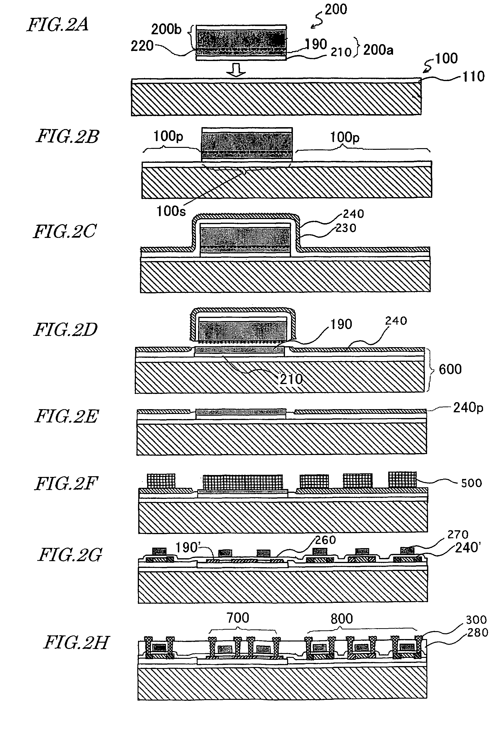
[0073]Hereinafter, a first specific preferred embodiment of the present invention will be described with reference to FIGS. 2A through 2H.

[0074]First, as shown in FIG. 2A, a supporting substrate 100 and a single crystal silicon substrate 200 are prepared. Although only one single crystal silicon substrate 200 is illustrated in FIG. 2A, the number of single crystal silicon substrates 200 to be bonded onto the single supporting substrate 100 does not have to be one but may be two or more.

[0075]In this preferred embodiment, the supporting substrate 100 is a glass substrate Code 1737 (produced by Corning Inc.) on which an SiO2 film 110 has been deposited to a thickness of about 100 nm. This SiO2 film 110 may be deposited by a plasma CVD process using tetraethylorthosilicate (TEOS) and oxygen gases. The SiO2 film 110 may be omitted depending on the material of the substrate. For example, when the glass substrate Code 1737 is used, it is not always necessary to deposit an insulating film ...

embodiment 2

[0098]Hereinafter, a second specific preferred embodiment of the present invention will be described with reference to FIGS. 3A through 3I.

[0099]First, as shown in FIG. 3A, a supporting substrate 100 and a single crystal silicon substrate 200 are prepared. Each of the supporting substrate 100 and single crystal silicon substrate 200 may have the same configuration as, and may be prepared by the same method as, the counterpart that has already been described for the first preferred embodiment with reference to FIG. 2A. In FIG. 3A, the first SiO2 film 210 of the single crystal silicon substrate 200 is illustrated as if the film 210 were thinner than the first SiO2 film 210 shown in FIG. 2A. Actually, however, these two films have approximately equal thicknesses. In this manner, the thicknesses and sizes of respective layers are not always to scale in not only FIG. 3A but also the other drawings as well. Thus, the present invention is in no way limited to the configurations illustrated...

embodiment 3

[0117]Hereinafter, a third specific preferred embodiment of the present invention will be described with reference to FIGS. 4A through 4H.

[0118]In the bonded substrate 602 of this preferred embodiment, a transistor structure including a single crystal silicon layer is defined on the first insulating layer 210 as shown in FIG. 4D unlike the bonded substrate 600 shown in FIG. 2D.

[0119]First, as shown in FIG. 4A, a supporting substrate 100 and a single crystal silicon substrate 201 are prepared. The supporting substrate 100 may have the same configuration as, and may be prepared by the same method as, the counterpart described for the first preferred embodiment with reference to FIG. 2A.

[0120]On the other hand, the single crystal silicon substrate 201 may be prepared in the following manner.

[0121]First, a first SiO2 film 210 is deposited to a thickness of 50 nm to 100 nm, for example, on the surface of a single crystal silicon wafer. In this preferred embodiment, the first SiO2 film 21...


PUM


Abstract

A semiconductor device includes a substrate with an insulating surface and a single crystal semiconductor layer, which is bonded to the insulating surface of the substrate. The device further includes a first insulating layer, which is provided between the insulating surface of the substrate and the single crystal semiconductor layer, and a second insulating layer, which has been deposited on the entire insulating surface of the substrate except an area in which the first insulating layer is present.

Description

BACKGROUND OF THE INVENTION[0001]1. Field of the Invention[0002]The present invention relates to a semiconductor device and a method for fabricating the device.[0003]2. Description of the Related Art[0004]An active-matrix-addressed display uses an active-matrix substrate on which a huge number of thin-film transistors (TFTs) are arranged in matrix. Those TFTs are integrated together on a substrate of an insulating material such as glass by thin film deposition, photolithography, and other manufacturing technologies similar to normal LSI manufacturing technologies. More particularly, a silicon thin film is deposited on a substrate by a CVD process, for example, and then patterned into a plurality of islands, which will be eventually used as active areas for respective TFTs.[0005]The TFTs fabricated in this manner are roughly classifiable into amorphous silicon TFTs and polysilicon TFTs according to the crystallinity of the silicon thin film to be used. The field effect mobility of a ...

Claims


Application Information

Patent Timeline
Patent Type & Authority Patents(United States)
IPC IPC(8): H01L27/01H01L27/08H01L21/02H01L21/20H01L21/316H01L21/336H01L21/762H01L21/77H01L21/84H01L27/12H01L29/786H01L31/0392
CPCH01L21/02164H01L21/02274H01L27/1266H01L21/76254H01L27/1214H01L21/31608B65B11/045B65B65/02F16C19/02F16C19/22F16C2361/71F16H7/06
Inventor TAKAFUJI, YUTAKAITOGA, TAKASHI
Owner SHARP KK
Why Eureka
Try Eureka