
Solid electrolytic capacitor element, solid electrolytic capacitor, and manufacturing method therefor

a technology solid electrolytic capacitor, which is applied in the direction of liquid electrolytic capacitor, capacitor dielectric layer, electrolytic capacitor manufacture, etc., can solve the problems of increasing esr, limiting the reduction of esr of solid electrolytic capacitor element, and inability to achieve sufficient contact resistance reduction, etc., to achieve the effect of reducing the contact resistance, and improving the adhesiveness of the dielectric layer

Active Publication Date: 2007-08-28
SANYO ELECTRIC CO LTD
View PDF4 Cites 16 Cited by
  • Summary
  • Abstract
  • Description
  • Claims
  • Application Information

AI Technical Summary

Benefits of technology

The use of a polyethylene glycol intermediate layer effectively reduces ESR in solid electrolytic capacitors by improving adhesiveness between the dielectric and electrolyte layers, resulting in a more efficient capacitor with lower ESR values.

Problems solved by technology

However, due to high contact resistance between a solid electrolyte layer and a dielectric layer, there is a problem of increasing ESR.
However, sufficient reduction of contact resistance could not be reached even with such structure, and there has been a limit in reducing ESR of a solid electrolytic capacitor element.

Method used


Image

  • Solid electrolytic capacitor element, solid electrolytic capacitor, and manufacturing method therefor
  • Solid electrolytic capacitor element, solid electrolytic capacitor, and manufacturing method therefor

Examples


embodiment 1

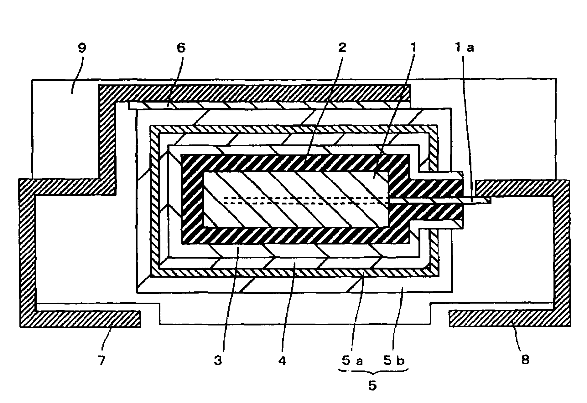
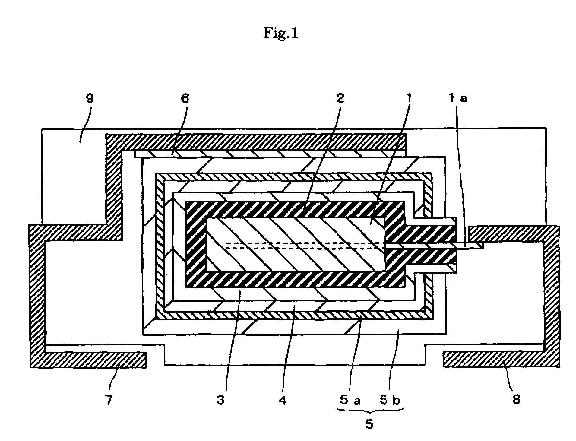
[0023]FIG. 1 is a cross section view of a solid electrolytic capacitor element of the current invention. A structure of the solid electrolytic capacitor element as it relates to the embodiment 1 of the current invention is hereinafter described.

[0024]First, as shown in FIG. 1, in the solid electrolytic capacitor element in the embodiment 1 of the current invention, a virtually plate-like anode 1 comprised of a tantalum porous sintered body that is fabricated by sintering tantalum powder with an average grain size of approximately 2 μm, in vacuum, is formed on an anode lead 1a comprised of tantalum so as to cover a portion of the anode lead 1a. At this time, the tantalum is an example of a “valve metal” and comprises the anode of the current invention.

[0025]A dielectric layer 2 consisting mainly of a tantalum oxide is formed on the anode 1, so as to cover an area surrounding the anode 1.

[0026]An intermediate layer 3 comprised of polyethylene glycol (hereinafter referred as PEG) havin...

embodiment 2

[0046]In this embodiment 2, a solid electrolytic capacitor element having a similar structure to that of the embodiment 1 was fabricated, except that instead of the intermediate layer 3 comprised of PEG with average molecular weight 1000 in embodiment 1 above using tantalum as an anode material, forming a intermediate layer 3 comprised of PEG with different molecular weights (molecular weights 100, 400, 800, 1200, 1500, 2000, 4000).

[0047]In this embodiment, solid electrolytic capacitor elements having a intermediate layer 3 comprised of PEG having a film thickness of between approximately 0.5 nm and approximately 20 nm in-between the dielectric layer 2 and the electrolyte layer 4 were fabricated respectively in the manner similar to that of embodiment 1, except that instead of using the aqueous solution containing PEG with a molecular weight of 1000 and approximately 0.001 wt % used in the embodiment 1, aqueous solutions containing PEG with molecular weights of 100, 400, 800, 1200, ...


PUM

PropertyMeasurementUnit
thicknessaaaaaaaaaa
thicknessaaaaaaaaaa
grain sizeaaaaaaaaaa

Abstract

The objective of the current invention is to provide a solid electrolytic capacitor element with low equivalent series resistance. In this solid electrolytic capacitor element, an anode including a porous sintered body, and a dielectric layer are sequentially formed on an anode lead so as to cover a portion of the anode lead. An intermediate layer including polyethylene glycol is formed on the dielectric layer so as to cover an area around the dielectric layer. An electrolyte layer that includes polypyrrole is formed on the intermediate layer so as to cover an area around the intermediate layer. A cathode that includes: a first electrically conductive layer mainly including graphite particles and a second electrically conductive layer mainly including silver particles is formed on the electrolyte layer so as to cover an area surrounding the electrolyte layer.

Description

TECHNICAL FIELD[0001]The current invention relates to a solid electrolytic capacitor element having an anode using a valve metal or an alloy consisting mainly of valve metal, a dielectric layer formed by anodizing the anode above, specifically, the current invention relates to, a solid electrolytic capacitor element with low equivalent series resistance (hereinafter referred as ESR), a solid electrolytic capacitor, and manufacturing method therefor.BACKGROUND OF INVENTION[0002]Solid electrolytic capacitors have widely been used for various electronic devices, specially in recent years, due to the necessity for instantaneously supplying current to a signal process circuit along with speed-up of signal process circuits of electronic devices, such as personal computers A solid electrolytic capacitor with lower ESR value at high-frequency area is desired. However, due to high contact resistance between a solid electrolyte layer and a dielectric layer, there is a problem of increasing ES...

Claims


Application Information

Patent Timeline
Patent Type & Authority Patents(United States)
IPC IPC(8): H01G9/04H01G9/00
CPCH01G9/0036H01G9/042H01G9/15H01G9/07Y10T29/417
Inventor IIDA, TAKAHISAYANO, MUTSUMITAKATANI, KAZUHIRONONOUE, HIROSHI
Owner SANYO ELECTRIC CO LTD
Learn More