CR oscillation circuit
a technology of oscillation circuit and oscillation frequency, which is applied in the direction of pulse generator, pulse technique, instruments, etc., can solve the problems of display flicker, increase in semiconductor integrated circuit cost, etc., and achieve the effect of suppressing clock frequency variation
- Summary
- Abstract
- Description
- Claims
- Application Information
AI Technical Summary
Benefits of technology
Problems solved by technology
Method used
Image
Examples
embodiment 1
[0040]
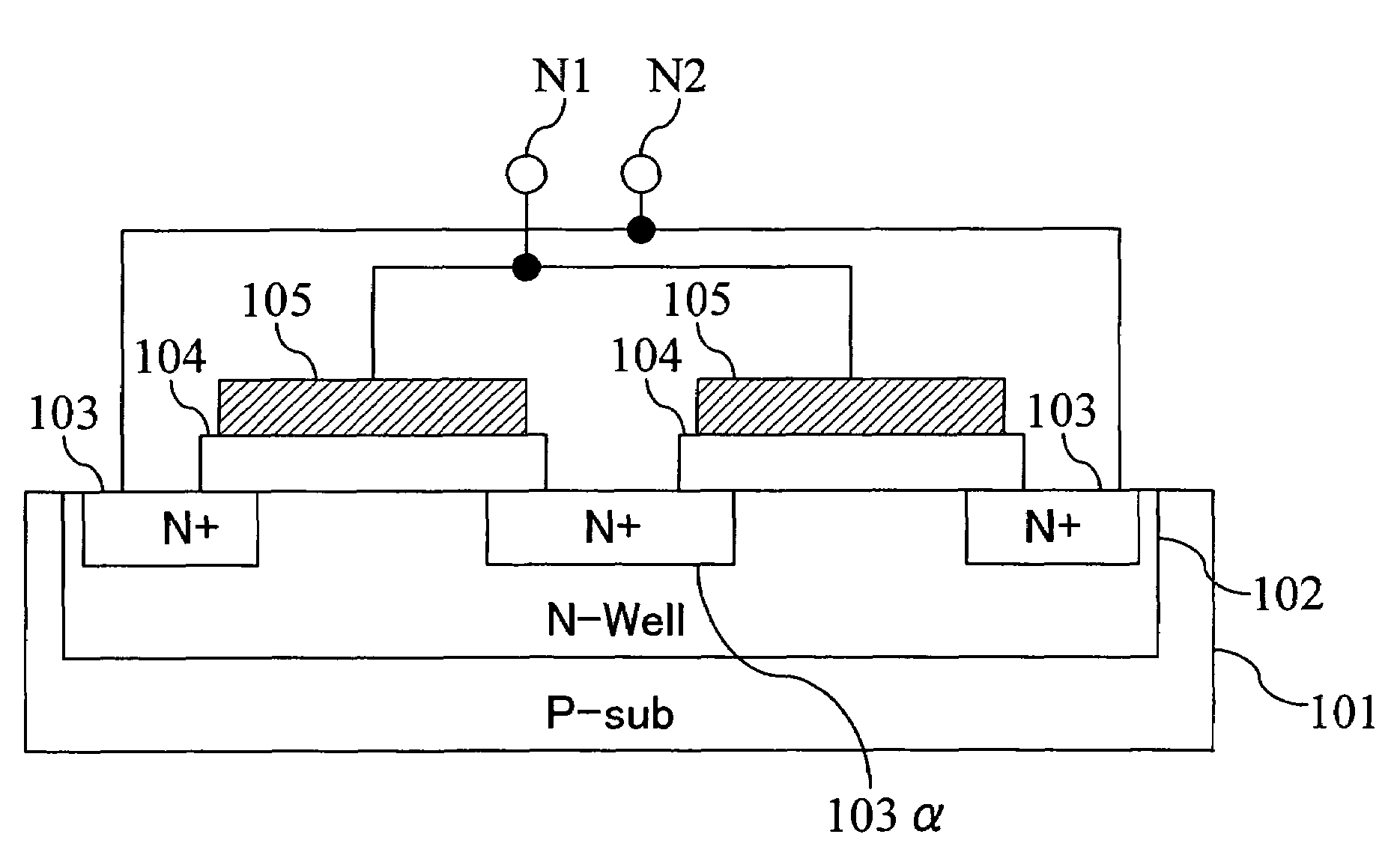
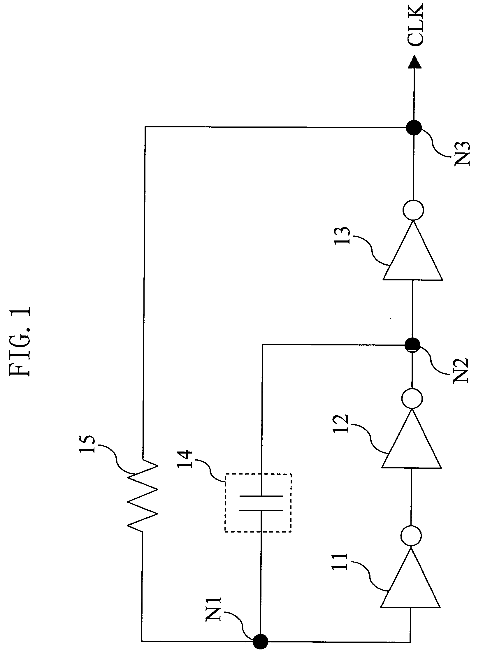
[0041]FIG. 1 is a circuit diagram of a CR oscillation circuit according to embodiment 1 of the present invention. This circuit includes inverters 11, 12 and 13, a capacitive element 14, and a resistive element 15. The inverters 11, 12 and 13 are connected in series between a node N1 and a node N3. The capacitive element 14 is connected between the node N1 and a node N2, which is a connection node between the inverter 12 and the inverter 13, in parallel with the inverters 11 and 12. The resistive element 15 is connected between the node N1 and the node N3 in parallel with the inverters 11, 12 and 13. The resistive element 15 is, for example, a polysilicon resistance.
[0042]In the CR oscillation circuit having such a structure, it has been generally known that the frequency of clock CLK output therefrom can be calculated by the formula of “1 / (2.2×C×R)” where C is the capacitance value of the capacitive element 14 and R is the resistance value of the resistive element 15. It shoul...
embodiment 2
[0071]
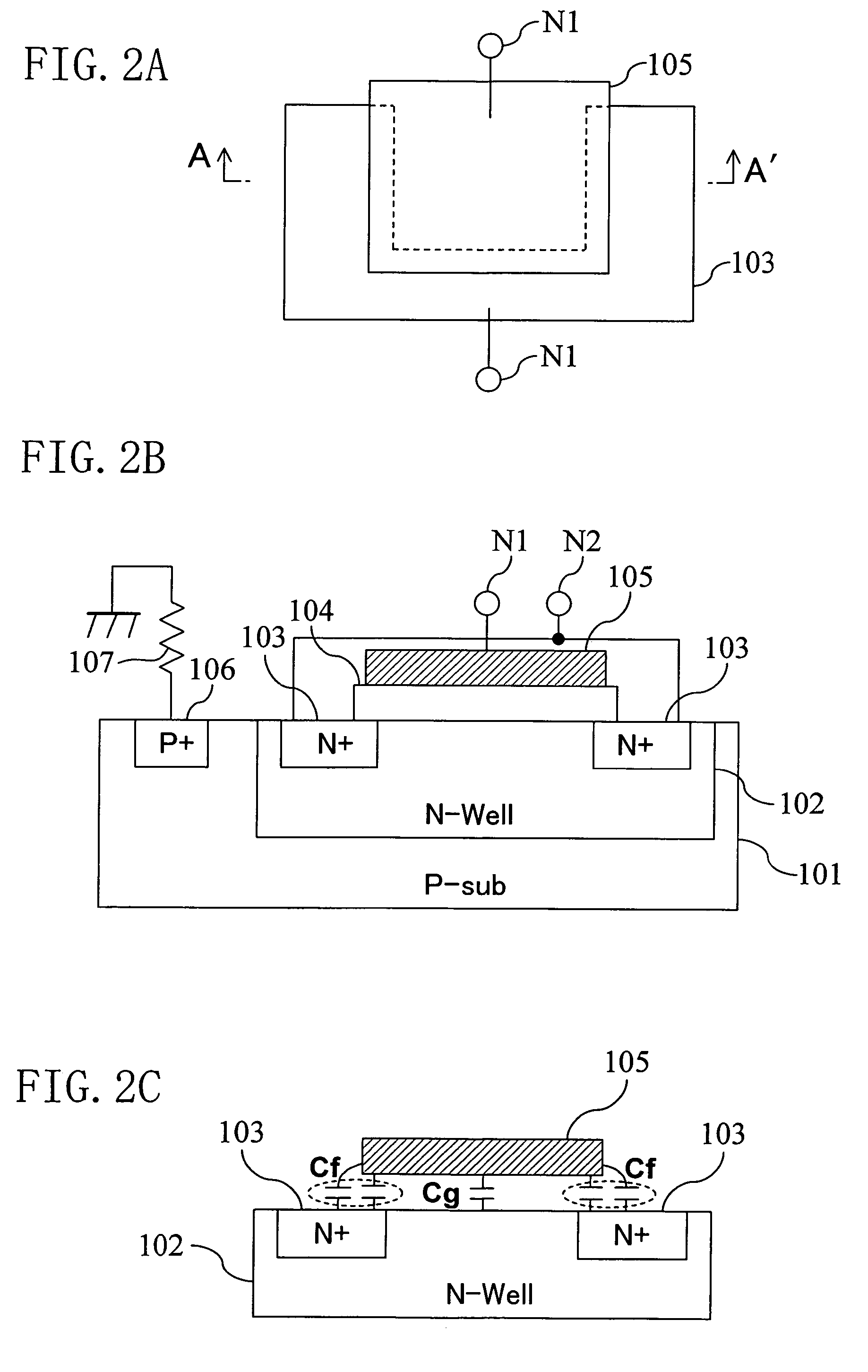
[0072]FIG. 6 shows the structure of a CR oscillation circuit according to embodiment 2 of the present invention. The CR oscillation circuit of embodiment 2 includes a capacitive element 24 and a resistive element 25 in place of the capacitive element 14 and the resistive element 15 of FIG. 1. The CR oscillation circuit further includes a P-type MOS transistor 26-P and an N-type MOS transistor 26-N. The other parts of the structure are the same as those of FIG. 1. The capacitive element 24 may be, for example, an interlayer capacitance, such as an interpolysilicon capacitance or intermetal capacitance, or may alternatively be the capacitive element (gate oxide film capacitance) shown in FIG. 2, FIG. 4 or FIG. 5. The P-type MOS transistor 26-P is connected between a node N4 and a power supply node, and the source and gate of the P-type MOS transistor 26-P are connected to each other. The N-type MOS transistor 26-N is connected between the node N4 and a ground node, and the sourc...
PUM
 Abstract
Description
Claims
Application Information
 - R&D
- Intellectual Property
- Life Sciences
- Materials
- Tech Scout
- Unparalleled Data Quality
- Higher Quality Content
- 60% Fewer Hallucinations
Browse by: Latest US Patents, China's latest patents, Technical Efficacy Thesaurus, Application Domain, Technology Topic, Popular Technical Reports.
© 2025 PatSnap. All rights reserved.Legal|Privacy policy|Modern Slavery Act Transparency Statement|Sitemap|About US| Contact US: help@patsnap.com


