Method and apparatus for low-speed, high-throughput fiber drawing using coiled fiber loops

a high-throughput, fiber-based technology, applied in the direction of paper, textiles, etc., can solve the problems of high waste volume, frequent fiber breakage and equipment stop, and fiber subject to a very abrupt acceleration and tension rise, and achieve high-performance fibers. high, high-speed drawing time t, low strain rate

Inactive Publication Date: 2007-09-25
POLYMER FIBER ENTERPRISE PARTNERSHIP
View PDF14 Cites 8 Cited by
  • Summary
  • Abstract
  • Description
  • Claims
  • Application Information

AI Technical Summary

Benefits of technology

[0045]In comparison with existing industrial processes, the invented drawing process has one or more of following advantages: significantly longer drawing time T, lower strain rate Vstain, and lower tension in the drawing line at the same or higher fiber speeds Voutlet and Vtake-up and throughput. This opens the door for substantial improvement of physical properties of commercial fibers, less breaks, less equipment stops, and less waste in comparison with the prior art in industrial fiber technology.OBJECTS OF THE INVENTION
[0049](b) requirement of the polymer fiber science—to provide long drawing time T and low strain rate Vstrain which are necessary to achieve the efficient “low oriented-high oriented polymer system transition” and to produce high-performance fibers. Drawing time T needs to be long enough (i.e., ranging from several seconds to several tens of seconds) to heat the fiber in the drawing process to the ambient elevated temperature with low temperature gradient and uniform morphology and physical properties in the fiber cross-section. Strain rate Vstrain needs to be at least one to two orders of magnitude lower than that in the industrial processes (i.e., ranging from several % / sec to several tens of % / sec).
[0050]2. Another object of the present invention is to provide a new industrial method and apparatus for continuous drawing of polymer fibers (both flexible-chain and wholly-aromatic) capable of substantially improving fiber tensile properties (i.e., tenacity, Young modulus, intermediate moduli, breaking elongation, etc.) approaching those obtained in laboratory experiments at low strain rate Vstrain and long drawing time T. In particular, this will result in development of a new generation of low-cost, high-performance industrial polymer fibers (most probably melt-spun, regular-molecular-weight, flexible-chain) having tenacity of about 1-2 GPa (12-22 gpd) and initial tensile modulus of about 20-100 GPa (250-1000 gpd) for different polymer fibers having different theoretical values of tensile properties.
[0051]3. Another object of the present invention is to provide a more reliable industrial process for continuous fiber drawing without abrupt, “impulsive” acceleration. This process will result in lower tension in the drawing line, less breaks, less equipment stops, and less waste than in the prior art.
[0052]4. An additional object of the present invention is to provide a new industrial method and apparatus for continuous fiber drawing which will produce dimensionally stable, low-shrinkage fibers without using expensive and energy-consuming additional equipment, while retaining improved physical properties, such as initial modulus, intermediate moduli, and tenacity, mentioned above. This may result in substantial saving in capital expenses, energy consumption, and possibility of smaller industrial space.
[0053]5. A further object of the present invention is to develop a new industrial method and apparatus for continuous fiber drawing (a) providing, in some cases, a substantial increase in the throughput in comparison with the existing industrial processes by increasing outlet speed Voutlet and take-up speed Vtake-up and (b) maintaining existing or improved physical properties, such as initial modulus, intermediate moduli, tenacity, and shrinkage, mentioned above.

Problems solved by technology

In such conventional high-fiber-speed, high-drawing-speed processes the fiber is subjected to a very abrupt acceleration and rise in tension at the point where it leaves one roller to pass to the succeeding higher-speed roller.
The “impulsive” acceleration and high tension result in frequent fiber breaks and equipment stops, high volume of waste, and preventing further fiber improvement.
This results in “non-equilibrium” drawing where the fiber does not have enough time to be heated to ambient elevated temperature while being drawn, and the drawing occurs at high temperature gradient in the fiber cross-section.
This, in turn, results in reduced drawability and crystallinity, high gradient of morphology and physical properties in the cross-section, high local overstresses, reduced tensile properties, and dimensionally unstable fibers with high hot-air shrinkage.
To provide additional time for heat setting, the existing technology requires a separate, specialized, very expensive, and energy-consuming equipment to produce dimensionally stable fibers without decrease of their tensile properties (U.S. Pat. No. 5,522,161 to Vetter (1996), U.S. Pat. No. 5,588,604 to Vetter et al.
The commercial drawing processes mentioned above do not enable one to produce polymer fibers with tensile and other physical properties close to those made by lab-scale low-fiber-speed, low-drawing-speed, long-drawing-time, and non-impulsive drawing process.
The great challenge for fiber science and technology is to fill this gap by producing industrially a new generation of low-cost, high-performance polymer fibers (most probably, flexible-chain, regular-molecular-weight, melt-spun) with substantially improved tensile and other physical properties.
In case of high-throughput processes, the drawing is “non-equilibrium”, i.e., it still has short drawing time (a few seconds), which is not enough to heat the fiber (especially high-denier fiber) to the ambient temperature in the process of drawing.
Thus, the incremental drawing is not uniform and may be termed “intermittent drawing”.
However, the invented method and apparatuses were not designed for and capable of fiber drawing.
However, this apparatus has some disadvantages with respect to implementation on the industrial scale.
(1) It is complicated in design having the diverged and skewed cantilever conveyer-drawing members (driven rollers) rotated about their exes and simultaneously about the central axis as a part of the winding rotating frame.
(2) The apparatus has a fixed angle of divergency of the conveyer-drawing members and is not capable to change the fiber draw ratio, if it is necessary, by changing the angle of divergency.
For the same reasons, Sordelli's apparatus has also limitations to be long to place large number of the loops.
Sordelli's apparatus has also limitations to provide large angle of divergency of the conveyer-drawing members and large diameter (and circumference) of the leading fiber loop at the delivery ends necessary for high draw ratios (5× and higher) because of design of the driving mechanism (gear box) to drive the conveyer-drawing members and possibility of sliding down of the fiber loops along the conveyer-drawing members (see below).
In that case, it would be difficult to find the coating that can operate inside a heat chamber at elevated temperatures necessary for effective hot drawing of the fibers.
(5) Sordelli's apparatus is not operator-friendly, i.e., it is difficult to load the fiber end into the apparatus to start the drawing process as well as to restart the apparatus after fiber breakage, and, in case of fiber breakage, the broken ends can be easily wound on the rotated conveyer-drawing members (rollers) resulting in significant operational problem.
Thus, the Sordelli's apparatus has substantial disadvantages to be industrially feasible.

Method used


Image

  • Method and apparatus for low-speed, high-throughput fiber drawing using coiled fiber loops
  • Method and apparatus for low-speed, high-throughput fiber drawing using coiled fiber loops
  • Method and apparatus for low-speed, high-throughput fiber drawing using coiled fiber loops

Examples


example 1

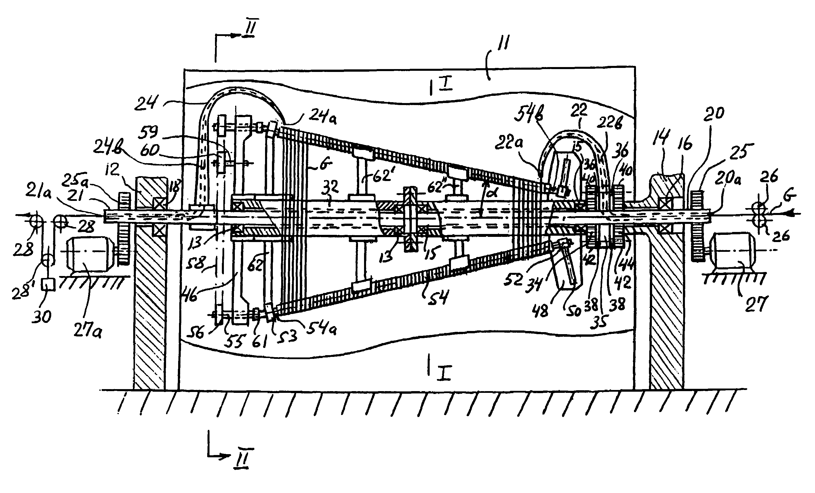
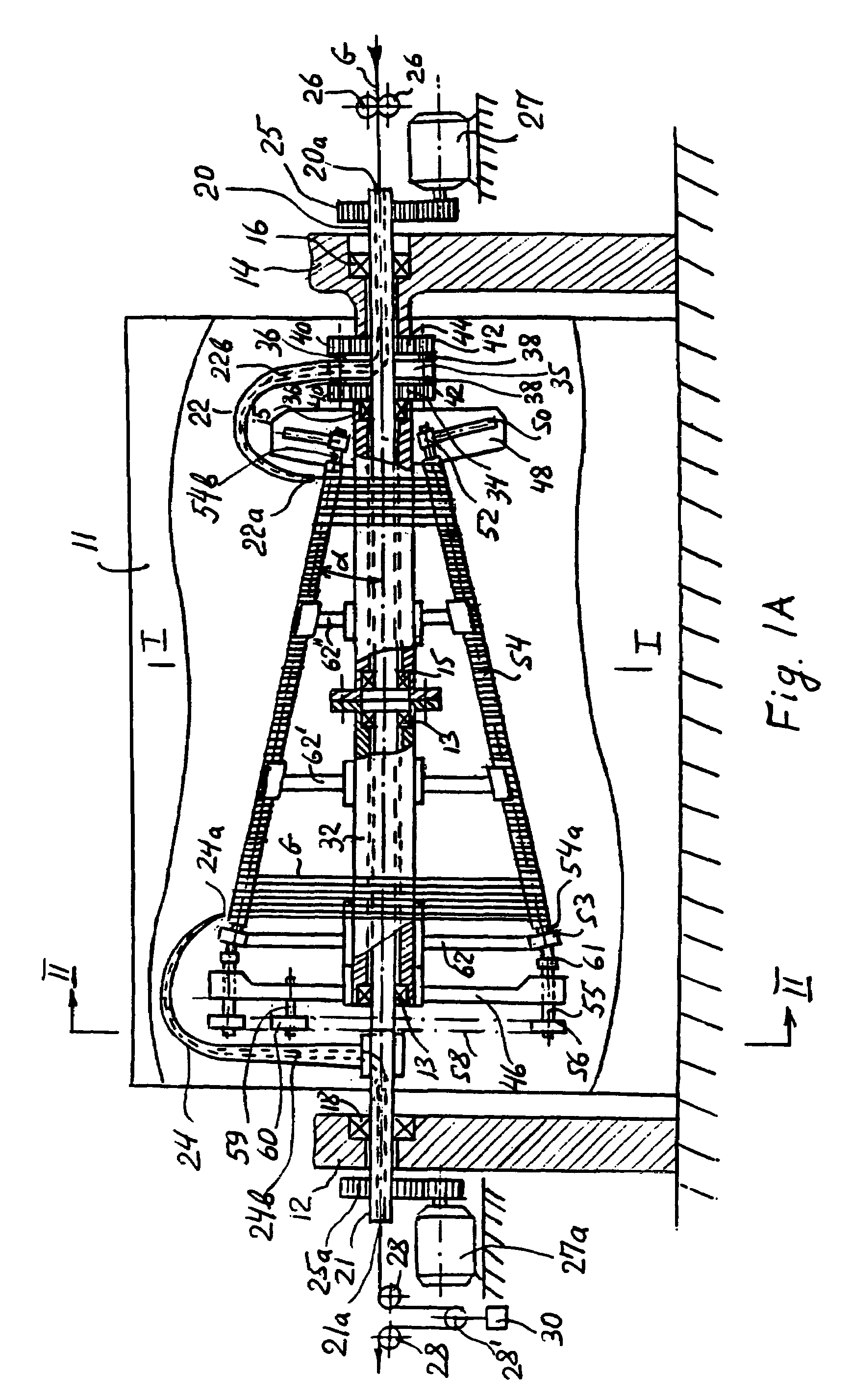
[0163]Table I gives the results of calculations for the case: L=5500 mm, Voutlet=Vtake-up=3000 m / min (the fiber is conveyed to the receiving package after the drawing stage), n=6, λ=5 to 1 (400%), and d, M and A are variable. The coiled fiber loops are not rotated about the central axis by the rotating rollers or spindles. Take-up speed of 3000 m / min is typical take-up speed for the commercial process for multifilaments and yarns.

example 2

[0164]Table II gives results of calculations for the case: L=2000 mm, Voutlet=Vtake-up==500 m / min (the fiber is conveyed to the receiving package after the drawing stage), n=6, λ=5 to 1 (400%), and d, M and A are variable. The coiled fiber loops are not rotated about the central axis by the rotating rollers or spindles. Take-up speed of 500 m / min is typical take-up speed for the commercial process for tape yarns and monofilaments.

(b) The Case of the Embodiment of FIG. 5A with the Coiled Serpentine Fiber Loops.

[0165]Equations (10)-(32) derived for the case of the coiled equilateral polygonal fiber loops (embodiments of FIGS. 1A-4A) are applicable for the case of the embodiment of FIG. 5A with the serpentine fiber loops where a number of the conveyer-drawing members n=2.

example 3

[0166]Table III gives the results of calculations for the case: L=5500 mm, Voutlet=Vtake-up==2000 m / min (the fiber is conveyed to the receiving package after the drawing stage), n=2, λ=5 to 1 (400%), and d, M and A are variable. Fiber points of the serpentine fiber loops are not moved by rotating rollers along the fiber axis. As discussed above, this embodiment of the invention having the serpentine fiber loops can draw multiple ends.

[0167]Thus, in the cases examined in Examples 1-3, fiber linear speed (Vfiber)max is low, i.e., 0.1-8 m / min, time of drawing T can reach tens of seconds, strain rate Vstrain is low, i.e., 6-70% / sec, and the ratio of Voutlet to (Vfiber)max is greater than 1 to 1, i.e., varying from the ratio 250 to 1 to the ratio 9000 to 1 (the fiber drawing apparatus can be constructed and arranged to provide the ratio, if necessary, lower than 250 to 1 and greater than 9000 to 1). In case of conventional commercial drawing process having the same λ=400% and (Vfiber)max...


PUM

PropertyMeasurementUnit
lengthaaaaaaaaaa
circumferenceaaaaaaaaaa
outlet speedaaaaaaaaaa

Abstract

A method and apparatus for continuous drawing of fibers in the form of coiled fiber loops (e.g., polygonal or serpentine loops). The successive fiber loops are continuously laid on receiving ends of a plurality of conveyer-drawing members (CDM) [e.g., rotating threaded spindles (54) or circulating endless chains (80) and (108)] disposed about a central axis and diverged from this axis. Coiled fiber loops are conveyed along the central axis and simultaneously drawn by enlarging a circumference of the fiber loops by the CDM. The leading fiber loops are continuously taken off at delivery ends of the CDM and conveyed from the drawing apparatus at an outlet speed. Heat chambers (11) and (148) envelop at least the most part of CDM. The process can operate at low drawing speed and long drawing time typical for lab-scale experiments and equal or higher outlet speed and throughput typical for commercial drawing processes. The method can produce low-cost / high-strength / high-modulus / low-shrinkage commercial polymer fibers.

Description

CROSS-REFERENCE TO RELATED APPLICATION[0001]This is a continuation-in-part of a prior-filed application (application Ser. No. 09 / 978,346, filing date—Oct. 16, 2001, status—abandoned).BACKGROUND OF THE INVENTION[0002]This invention relates to a method and apparatus for drawing fibers, yarns, or tapes formed from natural resin, synthetic resin, or combination of both. For the sake of convenience, in the description of this invention, which follows, the method and apparatus will be described in terms of drawing fibers. However, it is to be understood that the method and apparatus are equally usable for drawing any elongated body elements subject to such procedure. But for all that, the invented drawing method and apparatus will be described in terms of drawing of fibers in the form of coiled fiber loops. It is to be understood that the coiled fiber loops are a connected set of rings or twists into which the fiber can be wound.[0003]In the production of most polymer fibers (e.g., nylon,...

Claims


Application Information

Patent Timeline
Patent Type & Authority Patents(United States)
IPC IPC(8): D02J1/22
CPCD02J1/225D02J1/226D02J13/001
Inventor SLUTSKER, LEONIDMARIKHIN, VIACHESLAV A.MIASNIKOVA, LIOUBOV PETROVNA
Owner POLYMER FIBER ENTERPRISE PARTNERSHIP
Why Eureka
Try Eureka