Apparatus for controlling underwater based equipment

a technology of underwater equipment and apparatus, which is applied in the direction of sea energy generation, water power plants, tidal stream/damless hydropower, etc., can solve the problems of affecting the safety of underwater operations, the risk of collision damage to fish and marine mammals, and the unlikely ever-intentional pursuit of new tidal barrage systems

Inactive Publication Date: 2007-10-02
ROBERT GORDON UNIVERSITY
View PDF6 Cites 26 Cited by
  • Summary
  • Abstract
  • Description
  • Claims
  • Application Information

AI Technical Summary

Benefits of technology

[0021]It is an object of the present invention to obviate or mitigate the problems of controlling underwater equipment in a flowstream.

Problems solved by technology

The most powerful flows tend to occur in areas of restriction, either by width or depth, but for the same reasons are not suitable for widespread exploitation by large, fixed devices which require a minimum rotor area, and therefore water depth, to justify the costs of installation and maintenance.
It is assumed from the outset that new tidal barrage systems are unlikely ever to be pursued due to their inherent properties of high cost, delayed financial return, and serious environmental consequences.
There also exist operational environmental impacts common to all methods of tidal power generation, such as, an inherent risk of collision damage to fish and marine mammals, redirection of currents and the sediments and food particles contained within them, and shipping, particularly fishing.
The planning of such a tidal ‘farm’ would need to be accurately modelled for wake effects, as once installed, the monopile is expensive to re-site.
In addition, operational depth is restricted to the 20 m-35 m range.
Existing monopile support mechanisms for presenting a tidal turbine to the tidal currents are expensive, thus making only a few sites economically viable for power generation and requiring considerable sub sea engineering expertise.
The current monopile systems permit raising the turbines above water level for maintenance and repair, which is beneficial, but the long-term (i.e. 20 years) reliability and corrosion resistance of the necessary mechanism must be questionable.
Concerning the environmental and decommissioning issues, the impact of installation would be considerable, especially to the benthic flora and fauna, but subsequently the piles may become areas of shelter and therefore, populated.
At present, the arrangement is unlikely to be suitable for large power output installations due to the relative sizes of anchor, turbine and float.
On occasions of relatively high velocity tidal streams (e.g. spring tides), if the anchor holds, the turbine will be dragged lower in the water with the unwanted potential to collide with the seabed.
However, visual inspection would need to be frequent as the structure is likely to be subject to storm damage and fatigue loading of the cable, leading to possible loss of the supporting float and subsequent sinking of the device, or loss of anchorage and subsequent drifting.
Once sunk, the device would be open to damage by the oscillating tidal currents and could prove difficult to recover, whilst a drifting device would potentially cause damage to any other moored turbines in its path.
Due to the length of tether required and the random positioning of the device at any one time, this arrangement is not suitable for closely grouped tidal farms and a safe spread would fail to make economical use of the power available in a given area.
For the same reasons, this type of arrangement would present a hazard to all forms of shipping, large and small.
As a result of the constant oscillations and considerable number of moving parts, it is probable that this device will be subject to high dynamic loading and subsequent fatigue stress.
The upward stroke of the hydrofoils will tend to lift the device off the seabed and hence increase the possibility of it being washed away at high tidal stream velocities.
However, this cannot be confirmed until a launch / recovery mechanism is proposed.
Using high pressure oil as a means of power transmission does however introduce the possibility of pollution in the event of leakage.
With these existing systems and designs, it is a problem that their instabilities during operations as well as during launch and recovery, if possible, might cause damage.
In addition, since these systems are becoming larger and larger, the frequent installation and maintenance operations will become more and more difficult and expensive.

Method used


Image

  • Apparatus for controlling underwater based equipment
  • Apparatus for controlling underwater based equipment
  • Apparatus for controlling underwater based equipment

Examples


first embodiment

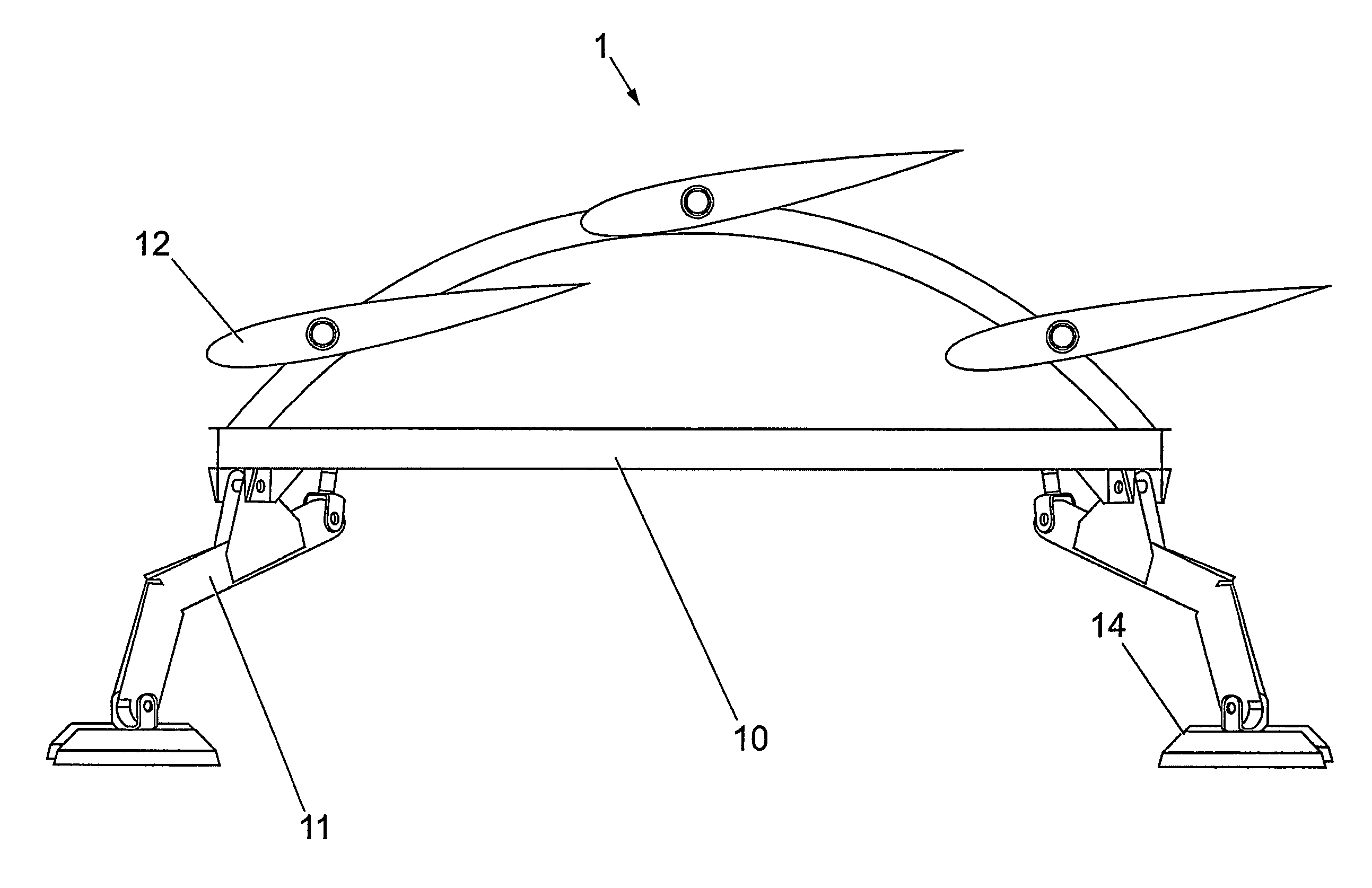
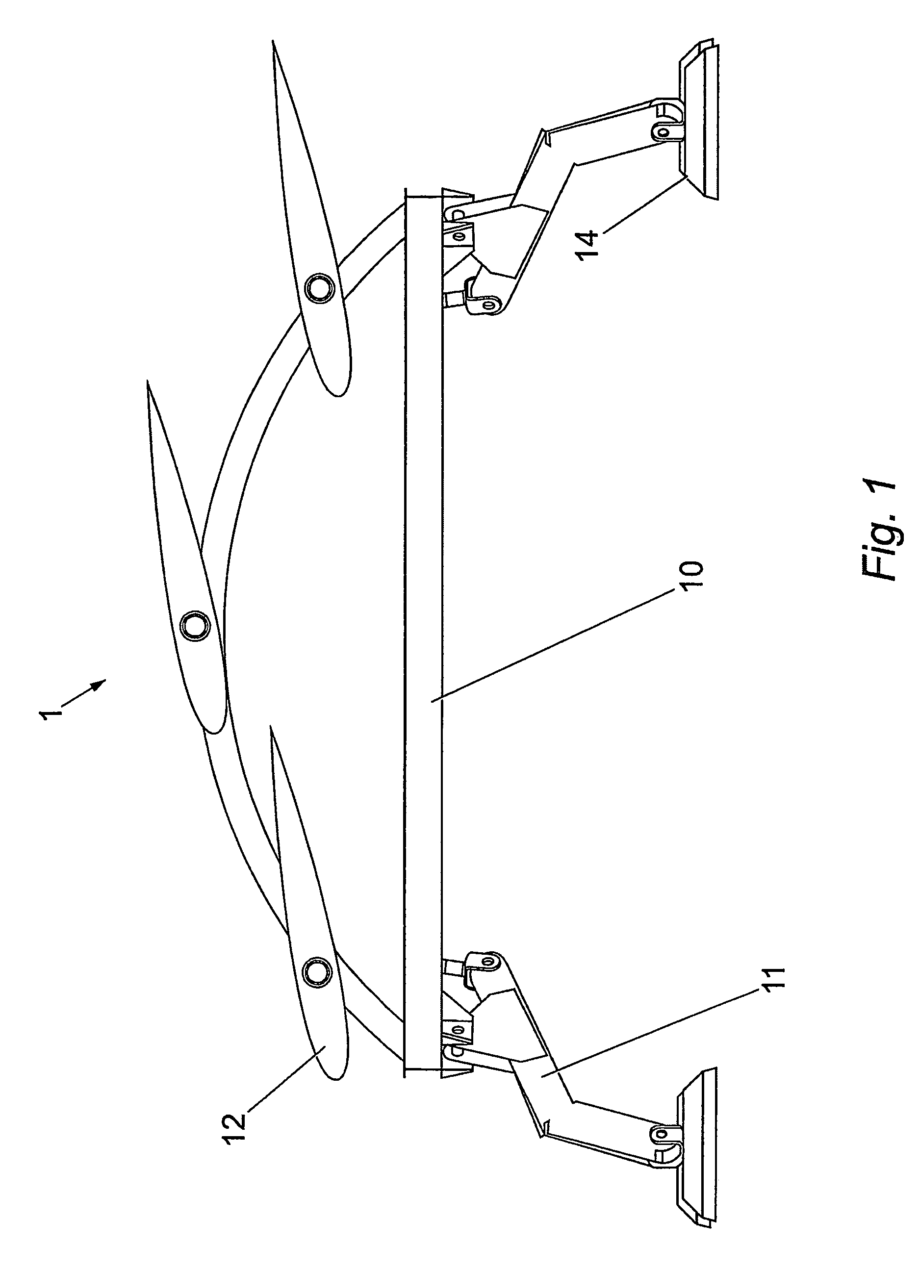
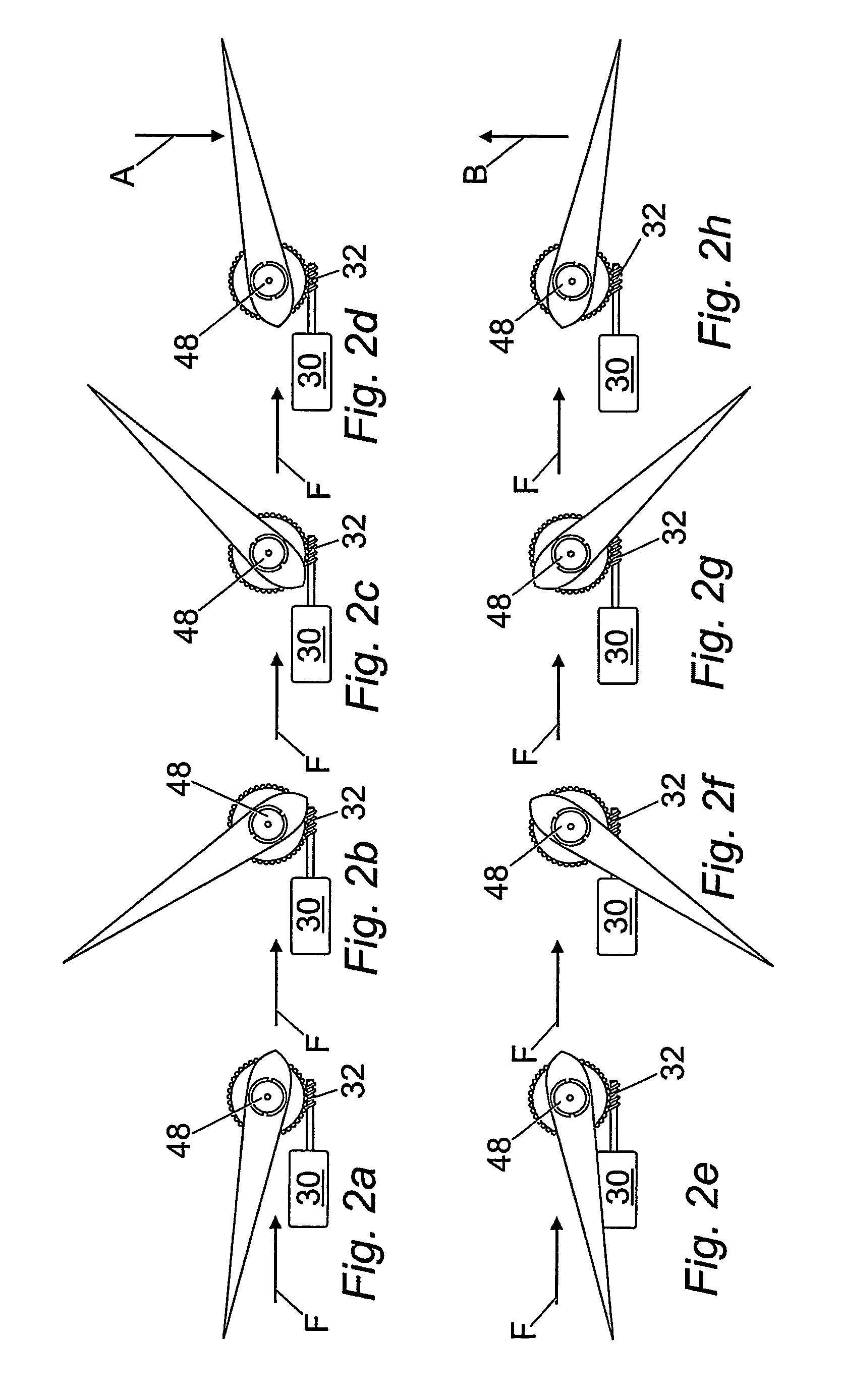
[0067]According to the present invention, the apparatus for launching an underwater device from a vessel, securing the underwater device whilst in operation on the seabed and permitting recovery to a vessel, for maintenance and repair should be as simple as possible without involving any sophisticated and specialised equipment. the invention is shown in FIG. 1 and utilises passive, self-rectifying static hydrofoils, the central shaft (see FIG. 3) of which can be rotated through 180° to generate positive or negative lift as required.

[0068]As is shown in FIG. 1, the apparatus 1 for controlling the launch, secure positioning and recovery of an underwater device comprises a space frame 10 for attaching to any desired underwater device such as power extraction equipment which may comprise a tidal turbine (not shown), a hydrofoil support frame to accommodate the self rectifying hydrofoil mechanisms 12 and hydraulically operated legs 11 for levelling of the apparatus 1. The feet 14 are equ...

second embodiment

[0083]an apparatus in accordance with the present invention is shown in FIGS. 5a-5d. The apparatus 100 comprises a tripod support frame 110, a bottom ring or stand 126, a disc-shaped hydrofoil 112, support brackets 120 and an attachment ring 122 with bolts 123. The apparatus 100 is attached to an ADCP canister 124 via the attachment ring 122 and bolts 123. Other subsea equipment may also be attached to the apparatus 100 in place of the canister 124.

[0084]The hydrofoil 112 is rigidly connected to the frame 110 via the support brackets 120 and its plane is generally parallel to the main plane defined by the bottom ring 126 such that the hydrofoil 122 will be generally parallel to the seabed in use. A central aperture 119 is provided within the hydrofoil 112. A lower face 113 of the hydrofoil 112 faces the stand 126 and is of a generally flat surface, whereas its opposite, upper, face 115 faces away from the stand 126 and gradually curves upwards away from the main plane of the hydrofo...


PUM


Abstract

The apparatus may include a space frame on which is mounted at least one hydrofoil for generating positive or negative lift. The frame is attachable to underwater equipment such as a turbine. The hydrofoils are adapted to produce negative lift when a flow of liquid passes over them and so in use cause the apparatus and attached equipment to sink to the seabed. The flow of water over the hydrofoils continue to produce negative life and so maintain the apparatus on the seabed. In certain embodiments, the hydrofoils can typically be set to a passive configuration in which they flip over when the current flow changes direction. Furthermore, the hydrofoils are selectively rotatable to provide an angle of attack such that they may be adapted to provide positive lift when it is necessary to remove the apparatus from the water.

Description

[0001]This Application is the U.S. National Phase Application of PCT International Application No PCT / GB2003 / 003845 filed Sep. 5, 2003.TECHNICAL FIELD[0002]The invention relates to an underwater location device such as may be used for controlling the launch, positioning or recovery of a tidal turbine or other underwater equipment. It should be noted that the example of a tidal turbine is used herein but the invention is not limited to such uses.BACKGROUND ART[0003]Tidal currents offer a considerable source of sustainable energy at various sites throughout the world, usually within easy reach of land and in relatively shallow waters. Tidal currents are created by movement of the tides around the earth producing a varying sea level, dependent on the phases of the moon and sun. As the sea levels vary, so the waters attempt to maintain equilibrium subject to gravitational forces, thus inducing flow from one area of sea to another. This flow is modified by a number of factors such as, th...

Claims


Application Information

Patent Timeline
Patent Type & Authority Patents(United States)
IPC IPC(8): E02B9/08F03B17/06
CPCE02B9/08F03B17/06Y02E10/28F05B2240/97Y02E10/30Y02E10/20
Inventor OWEN, ALANBRYDEN, IAN GORDON
Owner ROBERT GORDON UNIVERSITY
Why Eureka
Try Eureka