Multi-layered film window system

a film window system and multi-layer technology, applied in the direction of door/window protective devices, shutters/movable grilles, wing accessories, etc., can solve the problems of limited internal cover effectiveness, difficult to construct weather-tight, reliable, movable and reliable covers, etc., to promote solar heating and reduce solar gain

Inactive Publication Date: 2007-10-16
ANDERSON DONALD +1
View PDF20 Cites 74 Cited by
  • Summary
  • Abstract
  • Description
  • Claims
  • Application Information

AI Technical Summary

Benefits of technology

[0023]The individual films are preferably comprised of a mechanically strong and smooth plastic layer of the order of 0.001-inch to 0.005-inch in thickness. A plastic such as polyethylene terepthelate (e.g. MYLAR®) is one type of acceptable material. Both surfaces of each film are coated with a suitable material to provide a low-emissivity surface that is also high in solar reflectance. For example, a 1000-Angstrom “mirror” film of aluminum exhibits an emissivity below 0.035 and a solar reflectance above 0.85. Other materials such as gold or copper, etc. might be coated on each film. The surfaces may also be coated with non-metallic materials or mixtures of metallic and non-metallic materials. The opaque reflective coatings reduce visible light transmission and protect the carrier film from ultraviolet degradation. The coating materials may be applied over a variety of surface preparations, for example a matte finish will limit specular reflectance. The films can also be imprinted or embossed to provide decorative effects.
[0025]A control system for one or more windows along a single wall or specified walls of a defined space can be as simple as a wall-mounted switch calling for “window” or “wall” conditions. A control system might also permit manual control of desired roller assemblies to desired film travel positions, depending upon sensed thermal and solar conditions.
[0026]Another control system option is to provide occupancy sensors to control film movement to desired positions, depending upon room occupancy. Another option is to provide a control system that promotes solar heating during the heating season and reduces solar gain during the cooling season. Such a control system monitors differential between indoor room air temperature and instantaneous solar heating potential. Solar heating potential is measured by a temperature sensor mounted to a suitably constructed and oriented solar absorber.

Problems solved by technology

These losses occur during the heating season as a consequence of a low insulating rating and outward heat flow, mitigated by the solar gain of any windows and walls exposed to the sun.
The consequent rather bulky cover further precludes the application of such covers to curtain-wall structures, such as large buildings.
It is also difficult to construct such covers to be weather tight, movable, and reliable.
The effectiveness of internal covers is limited by a combination of factors including high infrared emissivity, air convection within the room spaces and leakage of air around and through window and wall surfaces.
None of them, however, have produced structures yielding R-values approaching that of a frame wall.
Some of these patents propose the use of metallized films or fabrics to decrease infrared emissivity to perhaps 0.3, but the structures suffer from problems of dust build-up and the necessity to frequently clean the surfaces and consequent vulnerability to damage.
While this “beadwall” approach has provided windows having reported R-values of the order of 20, several limitations exist.
The beads occupy significant storage space when the windows are emptied.
The glazing surfaces in contact with the beads tend to become covered with dust and statically suspended particles over time.

Method used


Image

  • Multi-layered film window system
  • Multi-layered film window system
  • Multi-layered film window system

Examples


Embodiment Construction

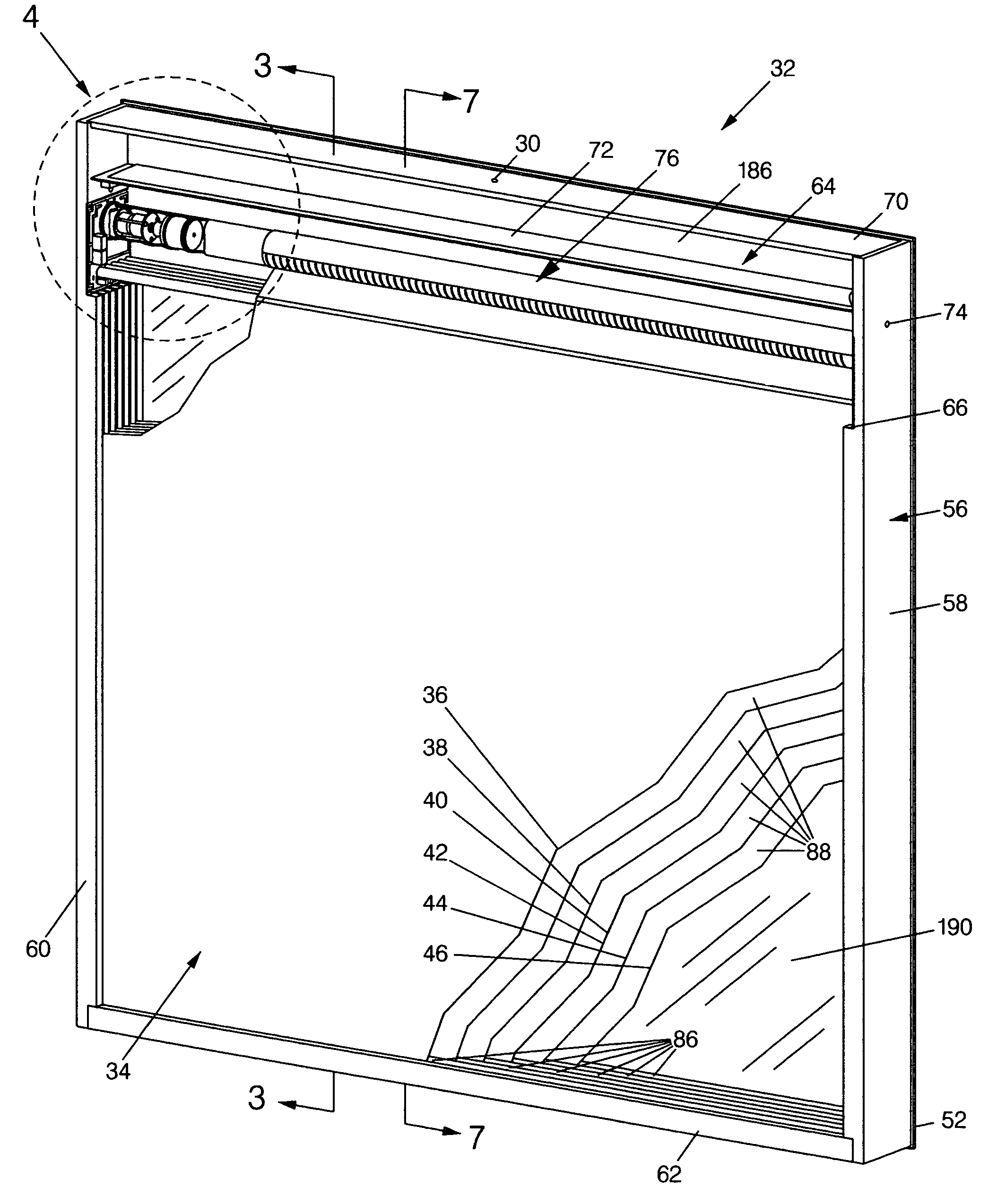
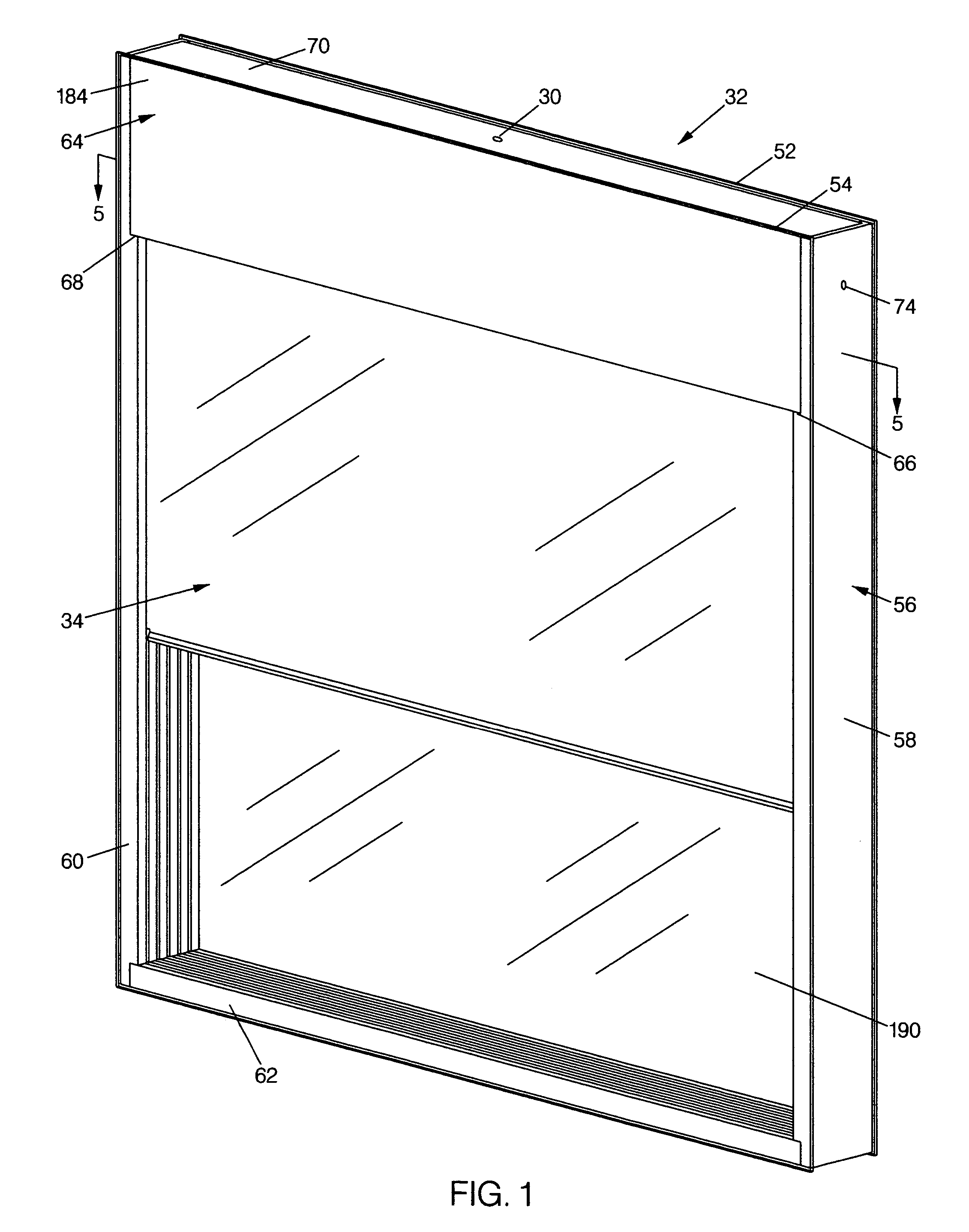
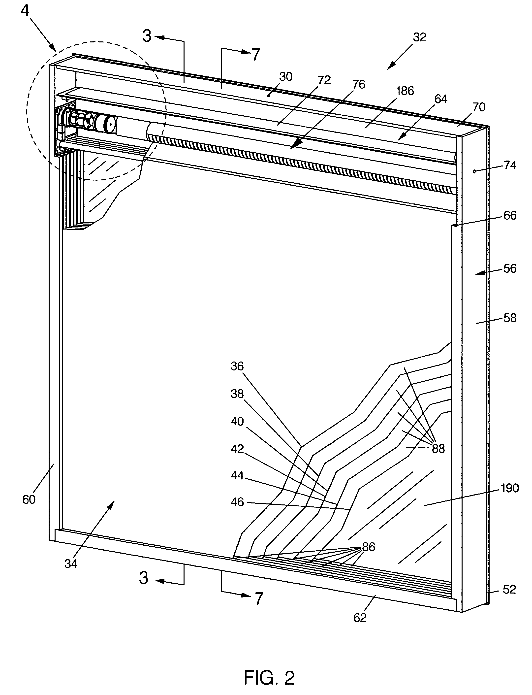
[0054]As generally noted above, the invention seeks to provide a sealed, glazed window assembly 32 having two layers of glass 52 and 54 or other suitably transparent material separated by several intermediate film layers 36–46. The assembly 32 is designed to demonstrate an insulation R-value on the order of a frame wall (e.g. R18 to R20). In contrast, a typical frame wall R-value of 19 is achieved with fiberglass bats fitted in a 6″ solid, opaque framed wall.

[0055]The significance of the capabilities of the assembly 32 can be appreciated upon consideration of the applicable physics relating to multi-layered glazed assemblies and available multi-layered windows. The physics of the assembly 32 derives from basic considerations that glass is transparent in the visible spectrum and a layer of glazing transmits approximately 95% of incident sunlight. A single layer of glass, which has a through-glass resistance of about 0.02 hrft2F / BTU has a measured R-value of about 1.0 hrft2F / BTU. This...


PUM


Abstract

A high R-rating window assembly storing multiple, reciprocating reflective flexible film layers in a sealed housing between rigid (e.g. glazed) layers. The glazed layers are separated on the order of 3 to 5-inches and are secured to low thermal conductivity framework pieces. The framework is capped with a motorized roller and film housing and the assembly is evacuated and filled with a desiccated, inert dry gas. Several plastic, reflective coated films are supported under tension in planar parallel relation between the glazing layers from the motorized roller and several guide rollers and guide tracks. Location sensors responsive to indicia on the films identify film position. Temperature sensors monitor ambient, internal and user set thermal conditions to control film exposure. The films are operable via a room control system and window controllers to define open, closed and partial exposure conditions. Alternative control functions may control film exposure in relation to room occupancy.

Description

BACKGROUND OF THE INVENTION[0001]The present invention relates to energy efficient windows and, in particular, to a sealed window having a plurality of suspended films and controls to extend and retract the films to control thermal efficiency.[0002]Energy loss through glazed surfaces comprises a significant part of a building's total energy loss, and can typically approximate 50% of the total loss. These losses occur during the heating season as a consequence of a low insulating rating and outward heat flow, mitigated by the solar gain of any windows and walls exposed to the sun. During the cooling season, inward solar heat flow detracts from the insulating characteristic of the building walls and windows, unless shading is employed.[0003]Attempts to improve the thermal transfer properties of glazed surfaces and particularly to decrease heat loss through glazed surfaces have in the past primarily consisted of shutters over the outer surface, for example, wooden “doors” from colonial...

Claims


Application Information

Patent Timeline
Patent Type & Authority Patents(United States)
IPC IPC(8): E06B9/08E05F1/04E06B3/00E06B9/264E06B9/32
CPCE06B9/32E06B9/264E06B2009/2643
Inventor ANDERSON, DONALDTAYLOR, CLIFFORD
Owner ANDERSON DONALD
Why Eureka
Try Eureka