Micromachined double tuning-fork gyrometer with detection in the plane of the machined wafer

a technology of micro-machined tuning forks and tuning forks, which is applied in the field ofinertial sensors, can solve the problems of high manufacturing cost, secondary mode not in dynamic equilibrium, and drawbacks of tuning fork architecture, and achieve high elongation resistance, low stiffness, and high elongation resistance.

Active Publication Date: 2007-10-23
THALES SA
View PDF5 Cites 80 Cited by
  • Summary
  • Abstract
  • Description
  • Claims
  • Application Information

AI Technical Summary

Benefits of technology

[0016]The detection mass is advantageously connected to the frame by at least two straight and elongate first flexure arms which have a high resistance to elongation in the detection direction and a low stiffness in the excitation direction,

Problems solved by technology

The tuning-fork architecture has a drawback: the secondary mode is not in dynamic equilibrium.
This double-fork structure has the drawback of being three-

Method used


Image

  • Micromachined double tuning-fork gyrometer with detection in the plane of the machined wafer
  • Micromachined double tuning-fork gyrometer with detection in the plane of the machined wafer
  • Micromachined double tuning-fork gyrometer with detection in the plane of the machined wafer

Examples


Embodiment Construction

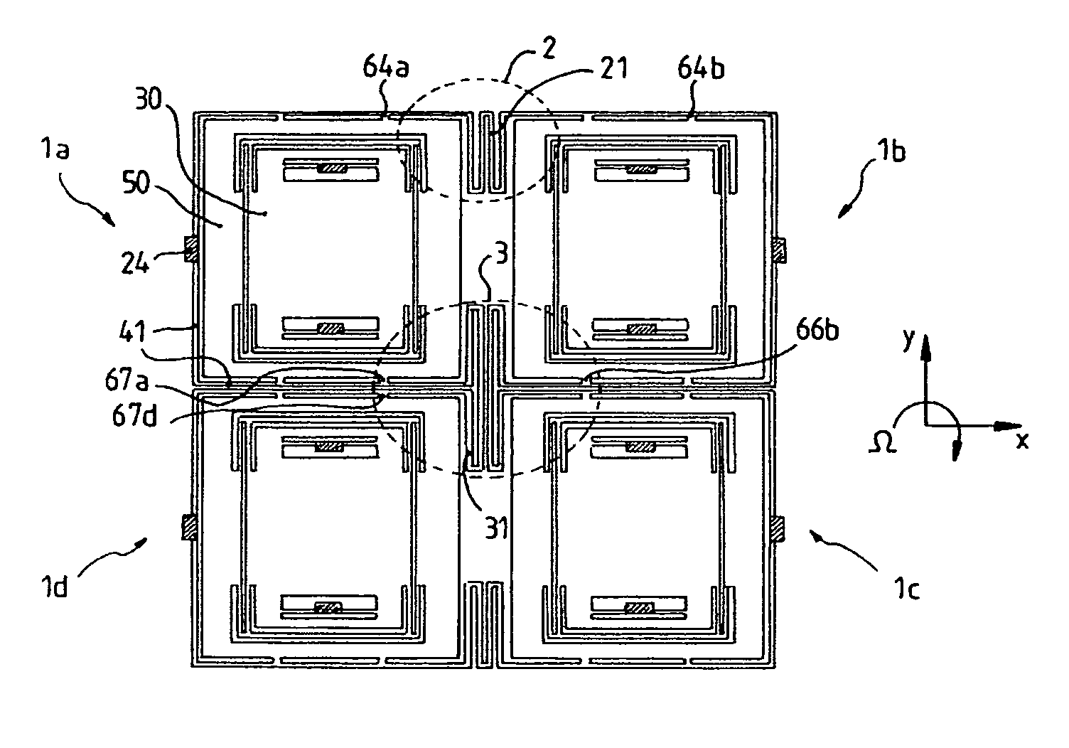
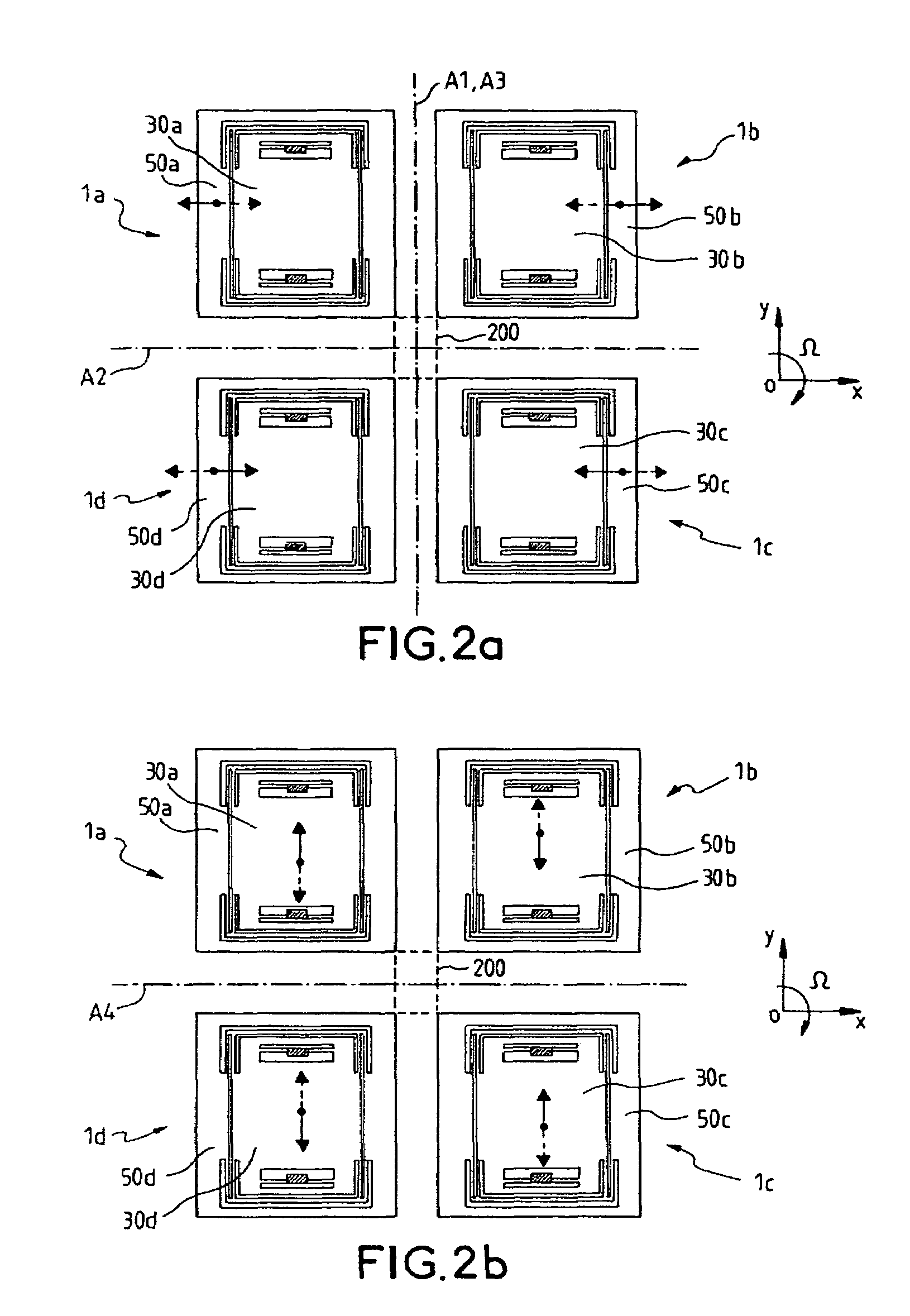
[0033]A thin planar silicon wafer is machined according to the invention in order to make a gyrometer whose sensitive axis is perpendicular to the plane of the wafer.

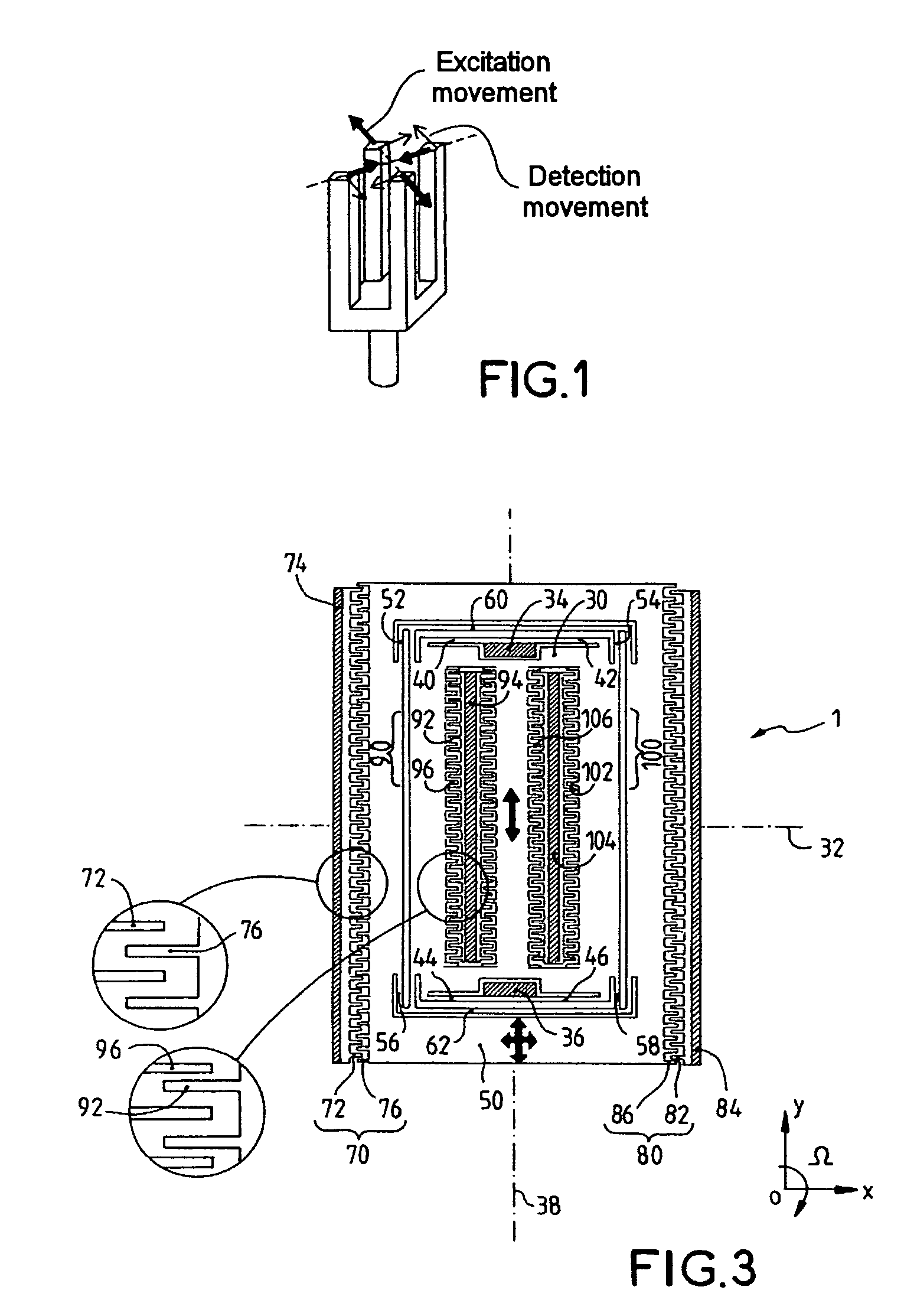
[0034]Silicon is chosen as preferred material, on the one hand for its mechanical properties and on the other for its high conductivity when it is sufficiently doped with an appropriate impurity (in general, boron in the case of p-type silicon). Conductive silicon makes it possible to produce the electrical functions of the gyrometer and especially the excitation functions and the detection functions; these functions are performed by interdigitated capacitive combs supplied with electrical current or voltage; the fingers of these combs, directly machined in the conductive silicon, serve as plates of capacitors useful for the excitation functions and for the detection functions.

[0035]The thickness of the starting silicon wafer is, for example, a few hundred microns; the wafer has, on the one hand, fixed anchoring zones f...


PUM


Abstract

The invention relates to a gyrometer based on a vibrating structure, produced by micromachining in a thin planar wafer. It comprises four moving assemblies placed at the vertices of a virtual rectangle, each moving assembly being coupled to two moving assemblies located at neighboring vertices via a coupling structure and comprising an inertial first moving element connected to the coupling structure and intended to vibrate in two orthogonal directions in the plane of the wafer, namely an excitation direction and a detection direction, and a second moving element intended to vibrate in the detection direction and connected, on one side, to the first moving element and, on the other side, to anchoring zones via linking means.

Description

RELATED APPLICATIONS[0001]The present application is based on, and claims priority from France Application Number 03 10609, filed Sep. 9, 2003, the disclosure of which is hereby incorporated by reference herein in its entirety.FIELD OF THE INVENTION[0002]The invention relates to inertial sensors intended for measuring angular velocities, or gyrometers, and more precisely to gyrometers that are micromachined using the technologies of etching, deposition, doping, etc., these being similar to those used in the field of integrated electronic circuits.[0003]Such micromachined inertial sensors produced on a silicon or quartz wafer are already known. The structure is planar in the plane of the silicon or quartz wafer in which it is etched.[0004]Structures based on two vibrating masses mechanically coupled in the manner of a tuning fork have already been produced. The structure of a gyrometer thus produced typically comprises two moving masses that are excited in vibration and connected as ...

Claims


Application Information

Patent Timeline
IPC IPC(8): G01C19/00G01P15/08G01P3/44G01P9/00G01C19/56G01C19/5747
CPCG01C19/5747
Inventor CHAUMET, BERNARDLEVERRIER, BERTRANDROUGEOT, CLAUDE
Owner THALES SA
Why Eureka
Try Eureka