High-Q micromechanical resonator devices and filters utilizing same

a micromechanical resonator and filter technology, applied in the direction of impedence networks, electrical devices, etc., can solve the problems of reducing the robustness and power reducing the efficiency of the overall system, and the removal of filters that do little to relax the requirements, so as to reduce mechanical losses to the substrate

Active Publication Date: 2007-11-13
RGT UNIV OF MICHIGAN
View PDF3 Cites 56 Cited by
  • Summary
  • Abstract
  • Description
  • Claims
  • Application Information

AI Technical Summary

Benefits of technology

[0055]In carrying out the above object and other objects of the present invention, a micromechanical resonator device having a desired mode shape is provided. The device includes a substrate and a hollow resonator having a central cavity and a stationary surface area. The desired mode shape is characterized by a plurality of interior nodal points located between the cavity and an outer periphery of the resonator. The desired mode shape involves movement of only a fraction of the stationary surface area at resonance. A non-intrusive support structure is anchored to the substrate and includes a hub disposed within the cavity and a plurality of spokes which radiate from the hub and support the resonator above the substrate to reduce mechanical losses to the substrate.
[0100]Yet still further in carrying out the above object and other objects of the present invention, a filter is provided which includes a substrate and a plurality of hollow resonators. Each of the resonators has a desired mode shape, a central cavity and a stationary surface area. The desired mode shape is characterized by a plurality of interior nodal points located between the cavity and an outer periphery of its resonator. The desired mode shape involves movement of only a fraction of the stationary surface area at resonance. The filter further includes a plurality of non-intrusive support structures. Each of the support structures is anchored to the substrate and includes a hub disposed within its respective cavity and a plurality of spokes which radiate from the hub and support its respective resonator above the substrate to reduce mechanical losses to the substrate. The filter further includes a mechanism for coupling the resonators together to form the filter.

Problems solved by technology

Although these methods can lower cost, they often do so at the expense of increased transistor circuit complexity and more stringent requirements on circuit performance, both of which degrade the robustness and power efficiency of the overall system.
In addition, the removal of the IF filter does little to relax the requirements of future multi-band reconfigurable handsets that will likely require high-Q RF filters in even larger quantities.
Specifically, small size leads to faster speed, lower power consumption, higher complexity, and lower cost.
However, as with nanoelectronics in the electrical domain, there are issues in the mechanical domain that might hinder the use of nanomechanical vibrating resonators for today's communication purposes.
In particular, excessive scaling may lead to “scaling-induced limitations,” such as adsorption-desorption noise [7], temperature fluctuation noise, and insufficient power handling, with the last of these perhaps being the most serious for present day applications.
As with nanoelectronics, the power handling issue with nanomechanical resonators really boils down to an impedance matching problem.
Unfortunately, RF channel-selection is extremely difficult, because it requires at least 0.1% bandwidth selectivity, which, in turn, requires filters using resonators with Q's >10,000 to maintain acceptable insertion loss (below 1 dB).

Method used


Image

  • High-Q micromechanical resonator devices and filters utilizing same
  • High-Q micromechanical resonator devices and filters utilizing same
  • High-Q micromechanical resonator devices and filters utilizing same

Examples


Embodiment Construction

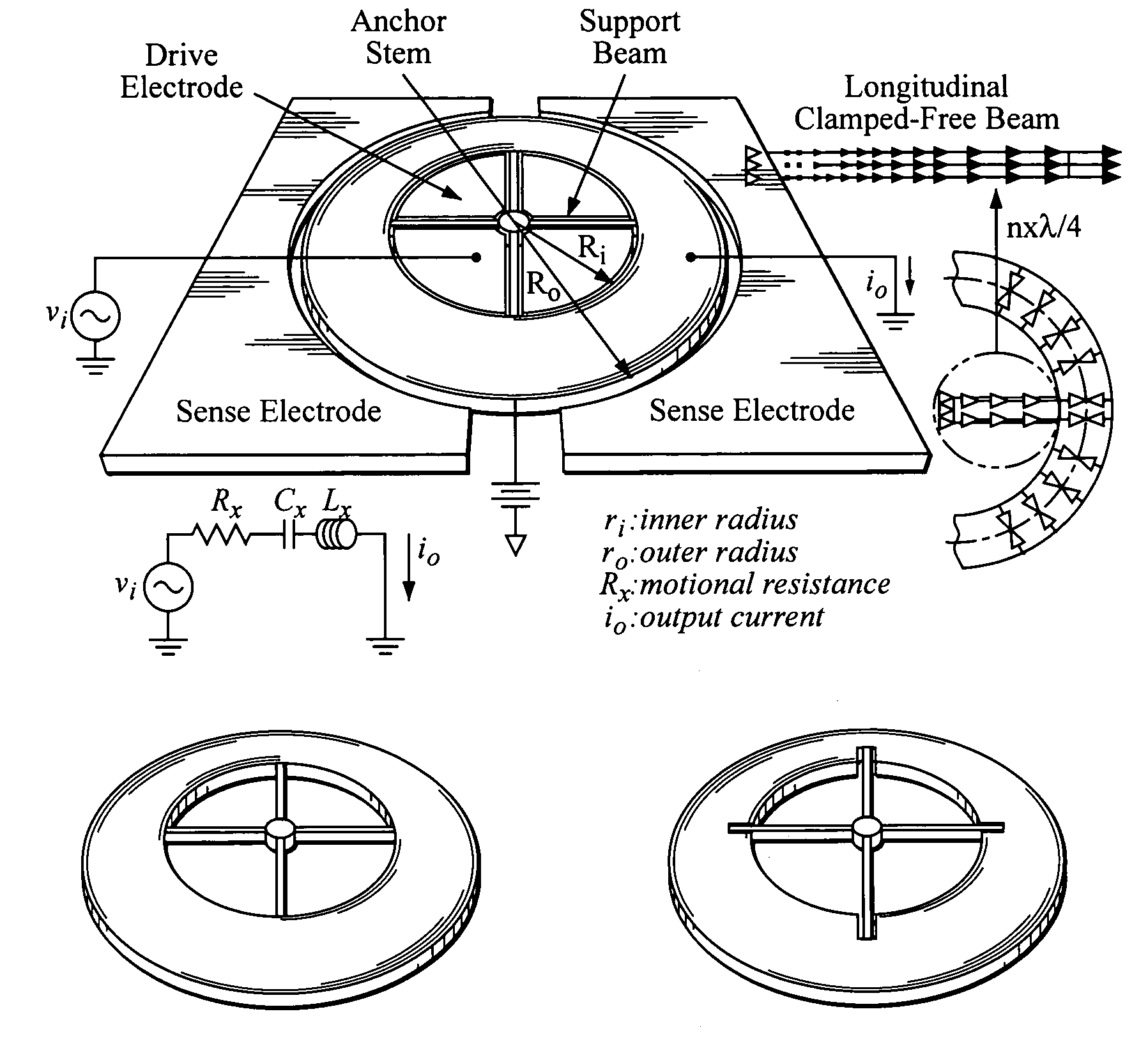
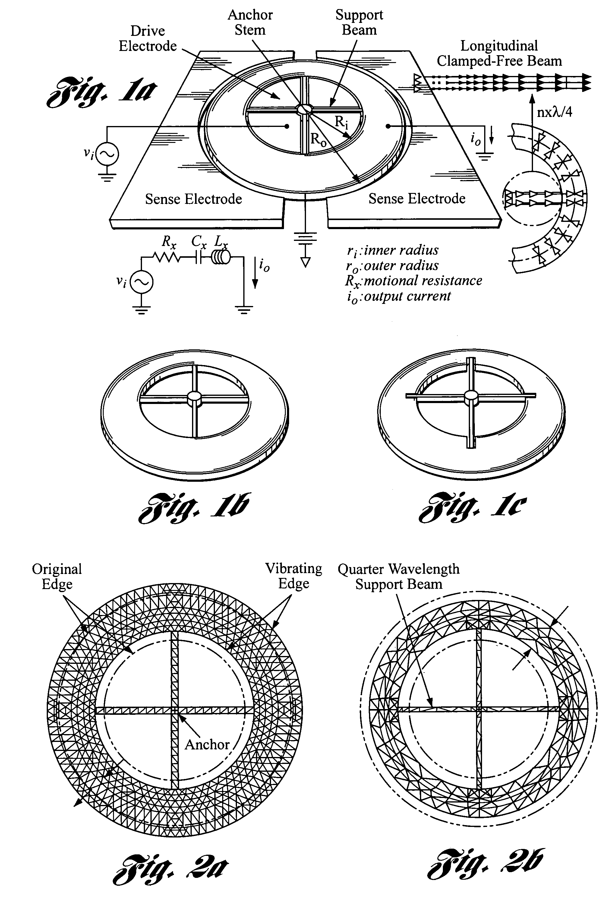
[0119]One embodiment of the present invention provides a radial ring resonator that uses a centralized support structure and notching at the support attachment locations that together greatly reduce support losses and allow polysilicon ring resonator Q's in excess of 10,000 at frequencies past 1 GHz. The specific design, shown in FIG. 1(a), is dubbed the “hollow-disk” ring resonator, since it is obtained by removing quadrants of material from a solid disk resonator [8], but purposely leaving intact beams or spokes of material to non-intrusively support the ring structure.

[0120]The hollow resonator has a central cavity in which a hub of material is disposed and supported on a stem. The beams or spokes radiate from the hub at their inner ends and support the resonator above the substrate at their outer ends.

[0121]Using an un-notched version of this design (i.e., FIG. 1b), several vibration modes have been demonstrated spanning frequencies from HF (24.4 MHZ), to VHF (72.1 MHZ), to UHF ...


PUM


Abstract

High-Q micromechanical resonator devices and filters utilizing same are provided. The devices and filters include a vibrating polysilicon micromechanical “hollow-disk” ring resonators obtained by removing quadrants of material from solid disk resonators, but purposely leaving intact beams or spokes of material with quarter-wavelength dimensions to non-intrusively support the resonators. The use of notched support attachments closer to actual extensional ring nodal points further raises the Q. Vibrating micromechanical hollow-disk ring filters including mechanically coupled resonators with resonator Q's greater than 10,000 achieve filter Q's on the order of thousands via a low-velocity coupling scheme. A longitudinally mechanical spring is utilized to attach the notched-type, low-velocity coupling locations of the resonators in order to achieve a extremely narrow passband.

Description

CROSS-REFERENCE TO RELATED APPLICATIONS[0001]This application claims the benefit of U.S. provisional application Ser. No. 60 / 537,822, filed Jan. 21, 2004 and entitled “Hollow Disk Micromechanical Resonator.”This application is related to application Publication No. 2004 / 0207492 A1 (now U.S. Pat. No. 6,985,051) and U.S. application Ser. No. 10 / 990,785, filed Nov. 17, 2004 and entitled “Micromechanical Resonator Device Having a Desired Mode Shape,” both of which are incorporated in their entirety by reference herein.STATEMENT REGARDING FEDERALLY SPONSORED RESEARCH OR DEVELOPMENT[0002]This invention was made with Government support from the National Science Foundation under Contract No. 9986866. The Government has certain rights in the invention.BACKGROUND OF THE INVENTION[0003]1. Field of the Invention[0004]This invention relates to high-Q micromechanical resonator devices and filters utilizing same.[0005]2. Background Art[0006]The following references are referenced herein:[0007][1] ...

Claims


Application Information

Patent Timeline
Patent Type & Authority Patents(United States)
IPC IPC(8): H03H9/02H03H9/46H03H9/48H03H3/007H03H9/24H03H9/50H03H9/54
CPCH03H3/0072H03H9/02338H03H9/2431H03H9/505H03H9/462H03H2009/02503H03H2009/02496
Inventor NGUYEN, CLARK T.-C.LI, SHENG-SHIAN
Owner RGT UNIV OF MICHIGAN
Why Eureka
Try Eureka