Method for removing oil from water coalescing in a polymer particle/fiber media

a technology of polymer particles and fiber media, which is applied in water/sewage treatment, ion exchange, separation processes, etc., can solve the problems of oil, grease and other hydrocarbons unavoidably spilling onto the deck area, and the surface of the ocean is swollen and contaminated, and achieves high liquid flow rate

Active Publication Date: 2007-11-20
AMCOL INTERNATIONAL CORPORATION
View PDF13 Cites 109 Cited by
  • Summary
  • Abstract
  • Description
  • Claims
  • Application Information

AI Technical Summary

Benefits of technology

[0010]The apparatus and methods described herein include apparatus for efficient contact of hydrocarbon-contaminated water with absorbent polymer particles carried by a fibrous carrier that permits relatively high liquid flow rates therethrough, and provides spacing of the polymer particles to provide maximum contact between the polymer particles and the hydrocarbon contaminant contained in the water for efficient coalescence of the hydrocarbons.
[0011]In accordance with one embodiment of the method, apparatus and polymer / non-woven fiber coalescing media described herein, an improved method and apparatus are provided for separating hydrocarbons from a liquid containing water and hydrocarbons, particularly an emulsion or stable dispersion of hydrocarbons and water. The apparatus includes an improved vessel that includes an inlet for conveying hydrocarbons, dispersed or emulsified in water, into the vessel and outlets for transporting separated water out of the vessel through the lower outlet, and coalesced hydrocarbons out of the vessel through the upper outlet. In the preferred embodiment, a removable header is connected to the upper or lower outlet and housed within the vessel. Permeable conduits are connected to the header and extend upward therefrom. Cartridges or canisters containing polymer particles homogeneously held throughout a fibrous particle capture and spacing media for coalescing hydrocarbon droplets are then stacked on the permeable conduits. Each cartridge includes a permeable outer cover and a permeable inner tube with the fibrous / polymeric particle capture media disposed therebetween. A pressure drop is provided between the vessel inlet and the vessel outlets, and therefore between the vessel inlet and the permeable conduits. As a result, the contaminated liquid flows radially outwardly through the inner tube of the cartridges, through the media and through the outer cover of the cartridge before flowing into the vessel. Intimate contact between the media and the contaminated liquid results in coalescence of the hydrocarbon contaminants. As the hydrocarbons coalesce and form larger oil droplets, the oil separates from the water in accordance with Stokes Law. The larger the coalesced oil droplets, the faster it separates from the aqueous phase. In the preferred embodiment, a header is detachably connected to the treated liquid outlet thereby facilitating removal of the header for replacement or servicing. Accumulated solids, which do not pass through the cartridges, are conveniently collected at the bottom of the vessel and can be flushed out through a drain valve.
[0018]Another aspect of the methods, apparatus and non-woven fiber / polymer particle coalescing media described herein is to provide a new and improved method and apparatus for coalescing oil, emulsified in water, for easy separation of the coalesced oil from the water, to achieve complete separation of oil from water admixed on an offshore oil well drilling or oil producing platform so that the separated water can be returned to the ocean without ocean contamination.
[0020]Another aspect of the methods, apparatus and non-woven fiber / polymer particle coalescing media described herein is to provide a new and improved method and apparatus for separation of organic liquids and water including a first gravity separation step that provides for separation of water and the organic liquids by settling to provide layering of the water in a layer below the organic liquid layer and then draining the lower water layer from the upper organic liquid layer, and thereafter directing the separated water layer through a vessel containing a coalescing media for coalescing the remaining organic liquid droplets entrained with the drained water layer for easy separation therefrom.

Problems solved by technology

The water insoluble and marginally water-soluble petroleum oil components may not be returned to the ocean in a concentration greater than 29 parts per million from an off-shore petroleum oil production facility because these materials have a tendency to separate from ocean water, due to the relatively low ocean water temperature, and agglomerate in the form of suspended droplets that result in a sheen on the surface of the ocean.
Higher concentrations of organics also cause toxicity concerns for the indigenous species in the sea.
During the recovery of oil at one or more of these work deck areas, oil, grease and other hydrocarbons are unavoidably spilled onto the deck area(s) and it is not permissible to discard these hydrocarbons into the ocean water.
The sump tanks presently used on offshore platforms suffer from a number of major drawbacks which result in significant amounts of hydrocarbons, particularly oil, paraffins, grease, and refined hydrocarbons being returned to the ocean causing significant ecological contamination.
One major drawback of the presently used sump tanks is that they are designed for a maximum of about three inches of rainwater per hour.
Another major drawback of the sump tanks presently used on offshore drilling platforms is that a tank containing a layer of oil disposed above a layer of water will lose the water by evaporation over an extended dry period and the oil layer, as a result, will coat the inside surfaces of the sump tank.
Another water treatment problem associated with offshore oil and gas producing platforms is the treatment of the aqueous solutions used in acid fracturing processes.
Specifically, acidic solutions are commonly pumped down under pressure to cause fractures in the oil producing regions of the formation.
As these acidic solutions are returned to the surface, they are often contaminated with oil or hydrocarbons.
Another problem associated with all auxiliary equipment used on oil platforms is the need for equipment to be designed in a space efficient manner.
Intimate contact between the media and the contaminated liquid results in coalescence of the hydrocarbon contaminants.

Method used


Image

  • Method for removing oil from water coalescing in a polymer particle/fiber media
  • Method for removing oil from water coalescing in a polymer particle/fiber media
  • Method for removing oil from water coalescing in a polymer particle/fiber media

Examples


Embodiment Construction

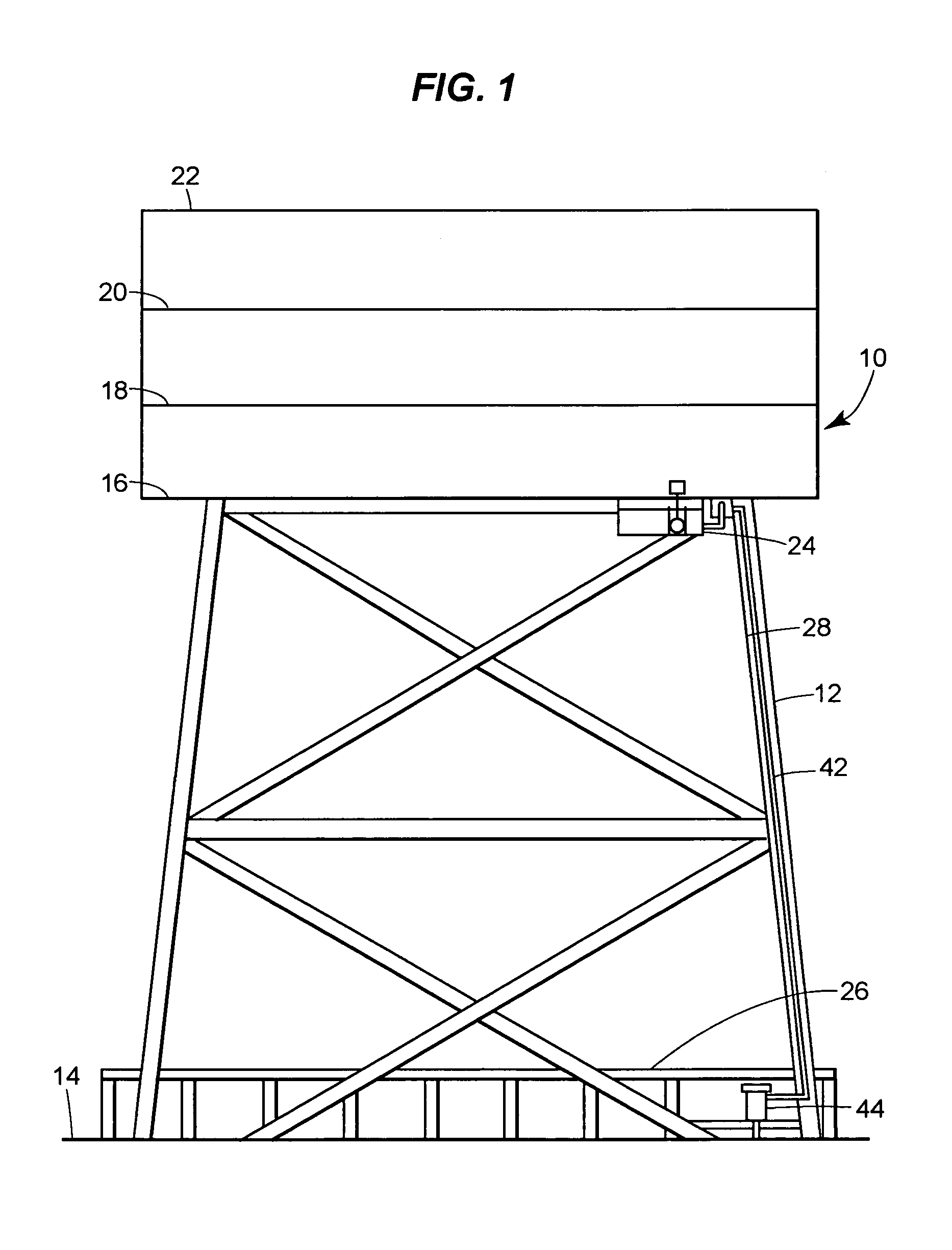
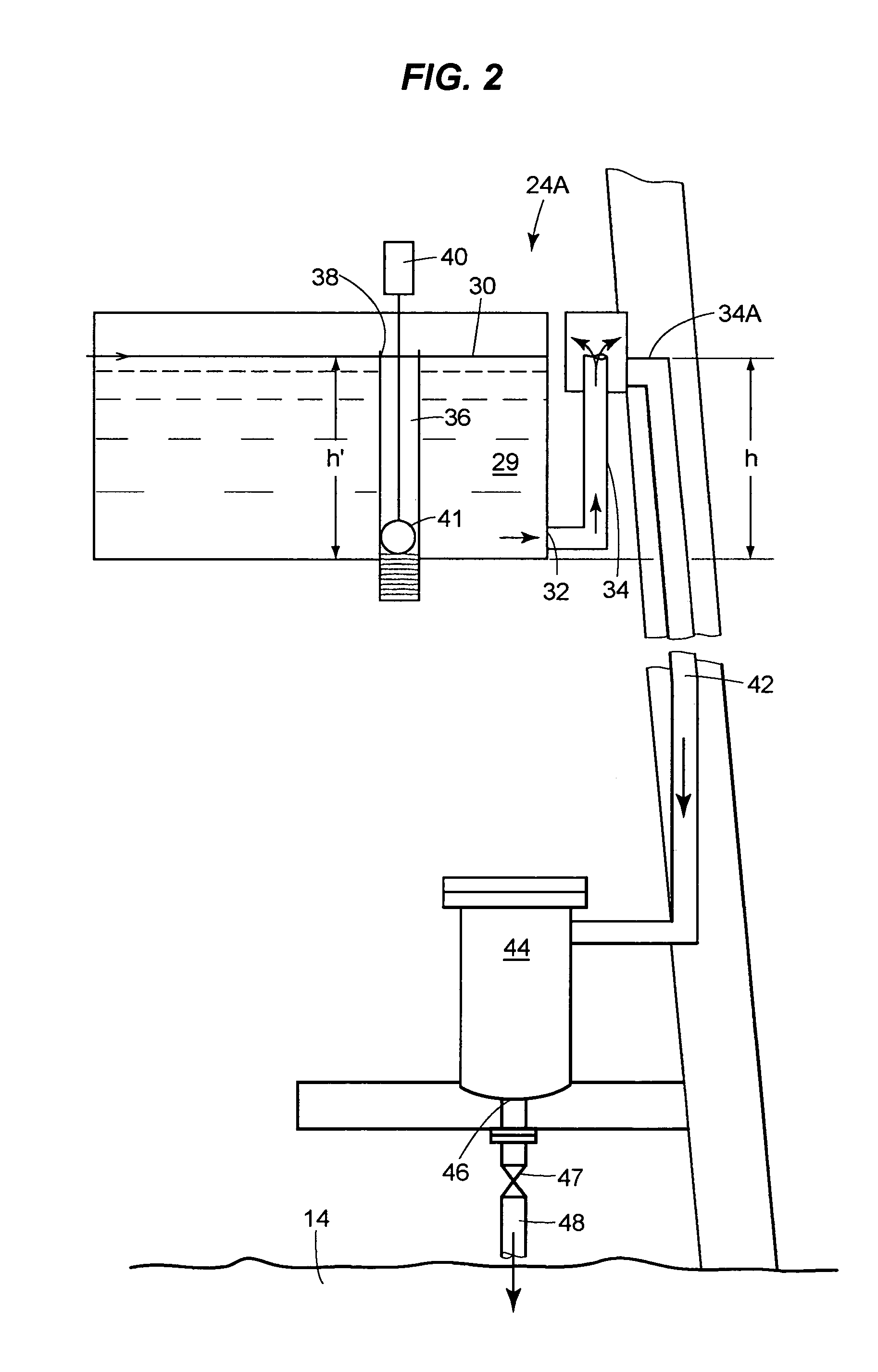
[0031]Turning now to the drawings, and initially to FIG. 1, there is shown an offshore drilling platform generally designated by reference numeral 10 including a work deck support structure 12 for supporting a plurality of stacked work decks at a substantial height above an ocean water level 14. The work decks commonly include a cellar deck 16 at a lowest work deck level, a second deck 18 located directly above the cellar deck 16, a third deck 20 disposed directly above deck 18, and a main deck 22 at an uppermost work deck level. In extant offshore drilling platforms, a sump tank 24 has been connected to the drilling platform 10 at the cellar deck level 16 and rainwater, including entrained hydrocarbons, particularly oil, paraffins and surfactants have been directed from all deck levels, which are contained so that rainwater and entrained hydrocarbons do not spill over to the ocean, to drain by gravity into the sump tank 24. It has been found that further separation of hydrocarbons ...


PUM

PropertyMeasurementUnit
particle sizeaaaaaaaaaa
densityaaaaaaaaaa
particle sizeaaaaaaaaaa

Abstract

Apparatus in fluid communication with a water leg portion of a hydrocarbon-contaminated water, e.g., a water leg portion of a produced water stream or an offshore drilling or production platform sump tank for conveying water, separated from oil, into contact with non-woven fiber / particulate polymer coalescing media-containing canisters such that the hydrocarbon droplets and other organic material droplets commingled with the sump tank or produced water will be coalesced by passage through the coalescing media. The canisters preferably are provided in a plurality of stacks in each vessel. Solids that do not pass through the canisters are accumulated at the bottom of the vessel and easily drained through a drain port. The water and hydrocarbons will pass through the coalescing media within the canisters and will be separated easily from each vessel, e.g., by gravity separation, sot that the water can be conveyed back to the ocean water without contamination.

Description

FIELD OF THE INVENTION[0001]The present invention is directed to an apparatus and method for separating oil, hydrocarbons and other organic materials from water, particularly industrial waste waters, ship bilge pump waters, produced water, deck drainage and rainwater collected on offshore oil drilling and production platforms, by coalescing the oil via contact with a polymer particle / fiber media. More particularly, the present invention is directed to an apparatus and method that preferably includes relatively crude, gravity separation of oil from the water and then contacting the separated water, containing a small amount of hydrocarbons, such as oil and grease, with polymer particles that are carried by non-woven fibers, for uniform distribution of the polymer particles therethrough, to coalesce the hydrocarbon droplets and separate the coalesced hydrocarbons from the water. Further, the present invention is directed towards a vessel for housing a plurality of cartridges containin...

Claims


Application Information

Patent Timeline
Patent Type & Authority Patents(United States)
IPC IPC(8): B01D17/02C02F1/28
CPCB01D17/045B01D17/10Y10S210/05
Inventor JOHNSON, MICHAEL R.OCCHIPINTI, JOHNDARLINGTON, JR., JERALD W.
Owner AMCOL INTERNATIONAL CORPORATION
Why Eureka
Try Eureka