

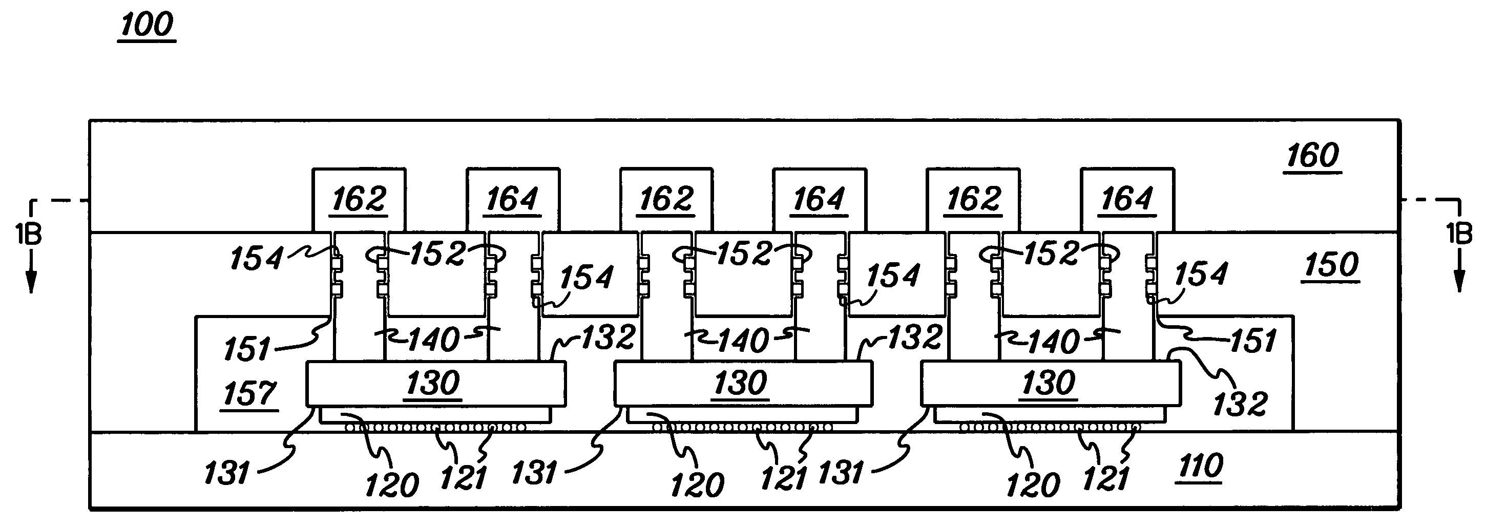
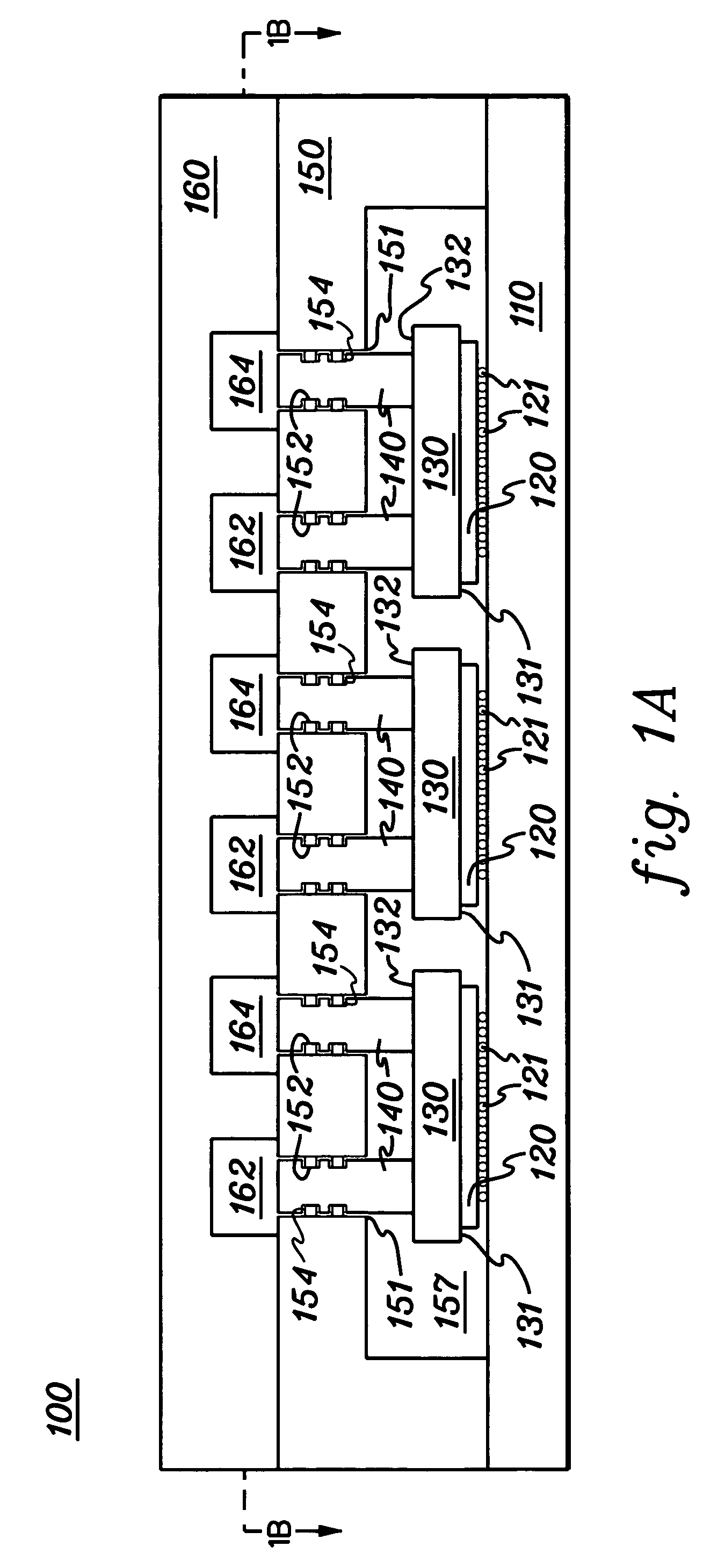
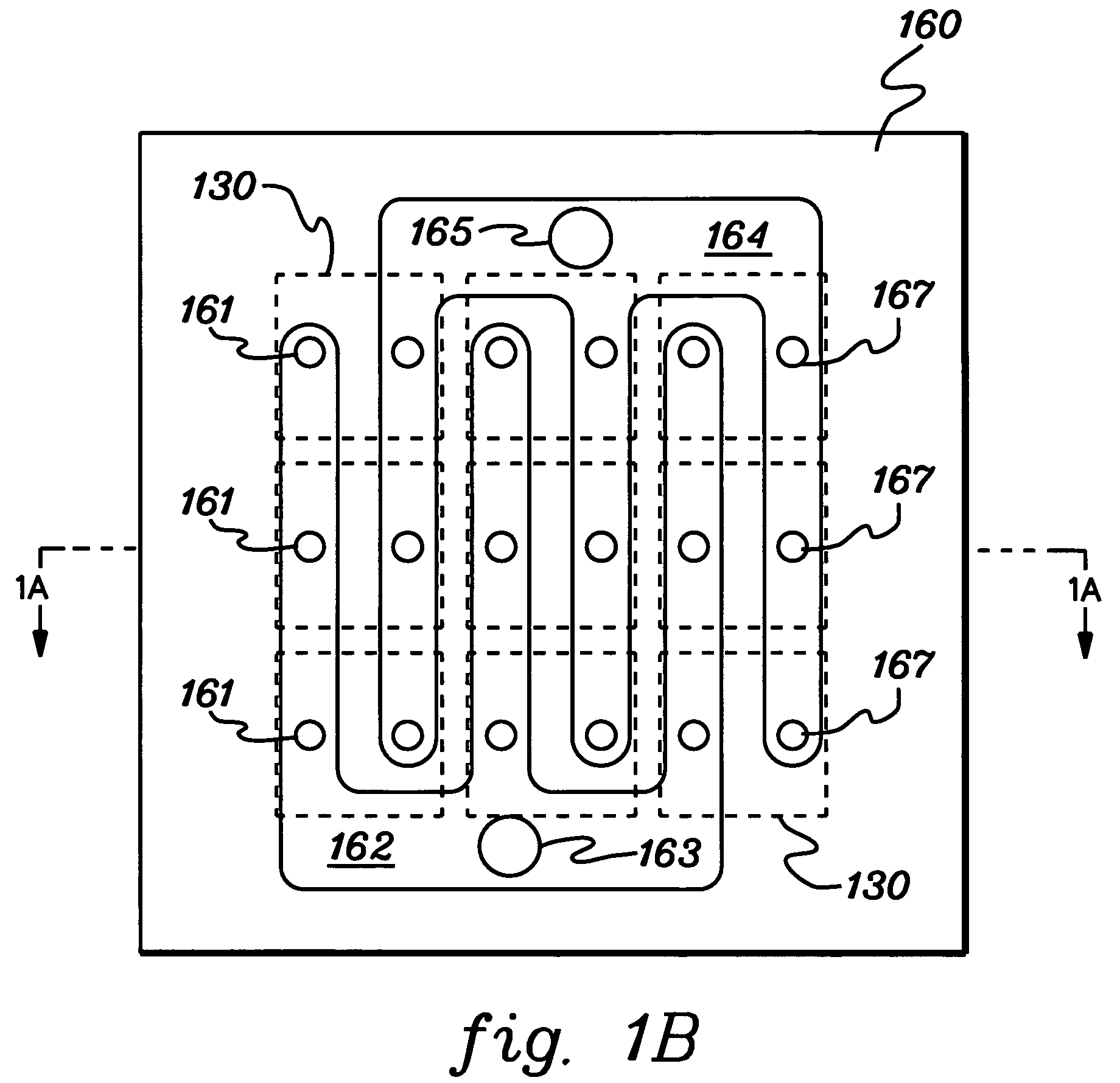
Cooling apparatus and method employing discrete cold plates disposed between a module enclosure and electronics components to be cooled
a technology of cooling apparatus and cold plate, which is applied in the direction of cooling/ventilation/heating modification, lighting and heating apparatus, semiconductor devices, etc., can solve the problems of increasing device temperature, thermal runaway conditions, increasing power dissipation, and therefore heat production
- Summary
- Abstract
- Description
- Claims
- Application Information
AI Technical Summary
Benefits of technology
Problems solved by technology
Method used
Image

Examples
Embodiment Construction
[0020]As used herein, “heat generating electronics component” may comprise any component of a computer system or other electronic system requiring cooling, and includes one or more integrated circuit devices, semiconductor chips, or other electronic circuitry requiring cooling. The “surface to be cooled” refers to a surface of the heat generating electronics component itself, or to an exposed surface of a thermal spreader, passivation layer, or other surface in thermal contact with the electronics component, and through which heat generated by the electronics component is to be extracted. A “micro-scaled cooling structure” means a cooling structure or cold plate with a characteristic dimension of 200 microns or less. A “biasing mechanism” refers to any biasing structure, such as one or more springs, leafs, etc., with a single spring arrangement per cold plate being illustrated in one embodiment provided herein by way of example only.
[0021]One example of coolant for a cooling apparat...
PUM
 Abstract
Description
Claims
Application Information