Photodetector having an electrostatic recording body and photodetecting method thereof

a photodetector and electrostatic recording technology, which is applied in the direction of optical radiation measurement, radiation controlled devices, instruments, etc., can solve the problems of increasing the current limitation of the size of the photodetector unit to about 1 inch, and achieves high sensitivity and high s/n ratio

Inactive Publication Date: 2007-11-27
FUJIFILM HLDG CORP +1
View PDF8 Cites 6 Cited by
  • Summary
  • Abstract
  • Description
  • Claims
  • Application Information

AI Technical Summary

Benefits of technology

[0016]In the photodetector and the photodetecting method using the same according to the present invention, the short-circuiting means is provided for short-circuiting between the first and second conductive layers. After the latent image charge is recorded, the first and second conductive layers are short-circuited by the short-circuiting means and are set at the same potential before irradiation of the readout light. Accordingly, a system where a larger current flows in a brighter portion of an image, i.e., a system of a positive type, is established. Therefore, the photodetector is hardly affected by a fluctuation component (shot noise) proportional to a square root of a detection signal, and there are no effects of power voltage fluctuation. As a result, a thin photodetector high in sensitivity and with a high S / N ratio can be achieved.

Problems solved by technology

However, since the Super-HARP image pickup tube has a vacuum-tube structure and needs electron beam scanning, the photodetector is increased in size, and a size of a photodetection unit is currently limited to about 1 inch.

Method used


Image

  • Photodetector having an electrostatic recording body and photodetecting method thereof
  • Photodetector having an electrostatic recording body and photodetecting method thereof
  • Photodetector having an electrostatic recording body and photodetecting method thereof

Examples


first embodiment

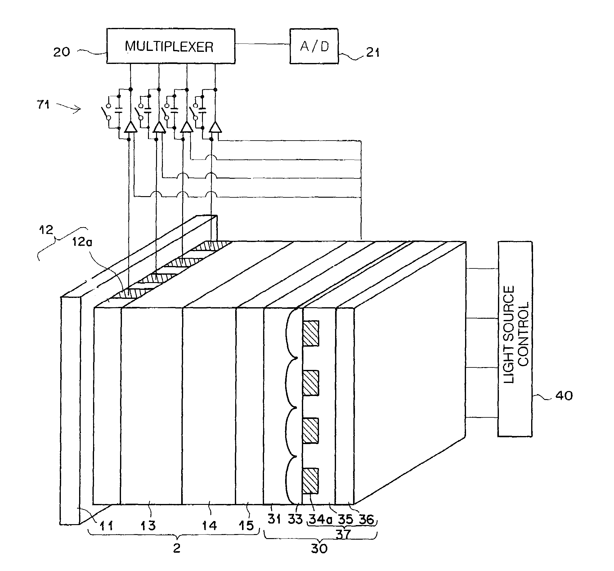
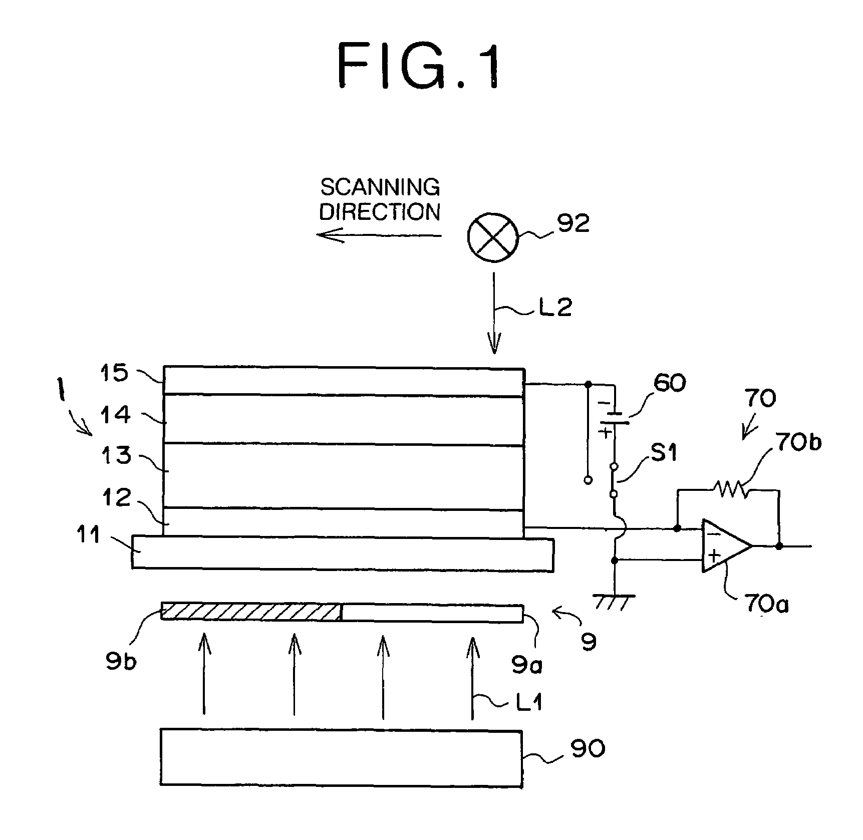
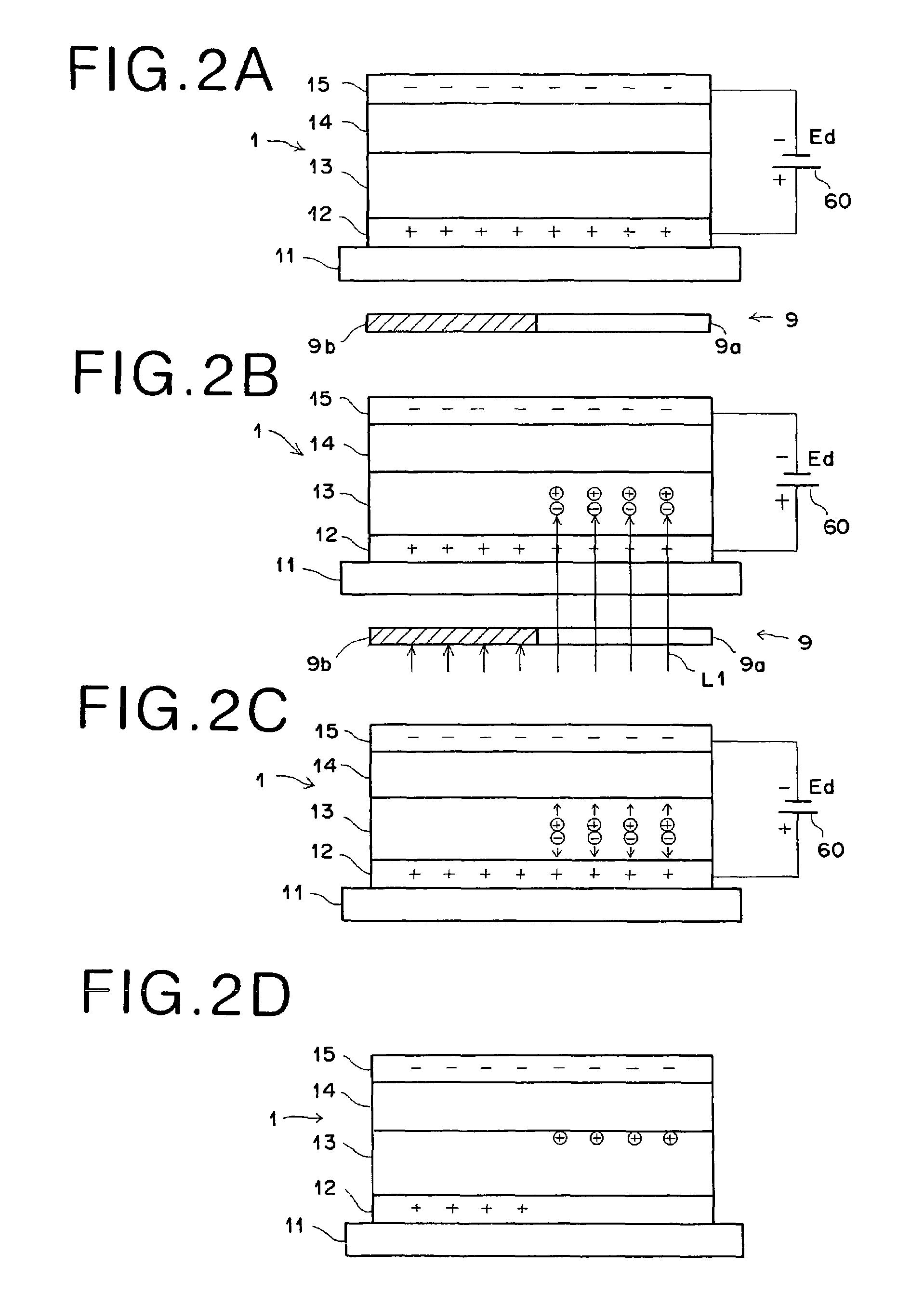
[0026]Next, description will be made of specific embodiments of a photodetector of the present invention with reference to the accompanying drawings. FIG. 1 is a schematic configuration view showing a recording and readout system (electrostatic latent image recording apparatus and electrostatic latent image readout apparatus are integrated) using a photodetector according to the present invention.

[0027]The recording and readout system includes an electrostatic recording body 1, recording light irradiating means 90, a power source 60, current detecting means 70, readout exposure means 92 and connecting means S1. The electrostatic latent image recording apparatus portion includes the electrostatic recording body 1, the power source 60, the recording light irradiating means 90, and the connecting means S1; meanwhile, the electrostatic latent image readout apparatus portion includes the electrostatic recording body 1 and the current detecting means 70.

[0028]The electrostatic recording b...


PUM

PropertyMeasurementUnit
thicknessaaaaaaaaaa
sizeaaaaaaaaaa
electric charge modelaaaaaaaaaa

Abstract

An electrostatic recording body is constructed by laminating a glass substrate transmissive of recording light, a first conductive layer transmissive of recording light, a photoconductive layer exhibiting conductivity by receiving recording light, an insulating dielectric layer, and a second conductive layer transmissive of readout light, in this order. DC voltage is applied to the electrostatic recording body by a power source to charge both conductive layers, and an object is irradiated with light from a recording light irradiating means, thereby recording a electrostatic latent image at an interface between the photoconductive layer and the dielectric layer. Then, the conductive layers are short-circuited and charged at the same potential, thereby redistributing electrical charges. Exposure is performed by scanning with readout light from a readout exposure means, and current flowing out of the electrostatic recording body is detected by a current detecting means, thus reading out the electrostatic latent image.

Description

BACKGROUND OF THE INVENTION[0001]1. Field of the Invention[0002]The present invention relates to a photodetector for performing photodetection with high sensitivity by using an amorphous selenium photoconductor, and to a photodetecting method using the photodetector.[0003]2. Description of the Related Art[0004]As a photodetector of high sensitivity with a high S / N ratio, an image pickup tube of a high-gain avalanche rushing amorphous photoconductor (Super-HARP) is currently being developed, which uses an amorphous selenium photoconductor as an image pickup tube photoconductive target (“Ultrahigh Sensitivity Super-HARP Image Pickup Tube”; pp. 1189-1198, Journal of Institute of Television Engineers of Japan, Vol. 46, No. 9). This Super-HARP image pickup tube can greatly increase a quantity of electric charges that can be taken out, by using the amorphous selenium photoconductor as a target and by applying a high voltage to the amorphous selenium photoconductor to cause avalanche ampli...

Claims


Application Information

Patent Timeline
Patent Type & Authority Patents(United States)
IPC IPC(8): H01L31/00G01J1/02G11B9/08G21K4/00H01L31/0248H01L31/08
CPCG03G15/758H01L31/09H01L31/0272G11B9/08G03G2215/00957
Inventor SHOJI, TAKASHI
Owner FUJIFILM HLDG CORP
Why Eureka
Try Eureka