Surface acoustic wave apparatus and communications device

a surface acoustic wave and apparatus technology, applied in piezoelectric/electrostrictive/magnetostrictive devices, semiconductor devices, piezoelectric/electrostriction/magnetostriction machines, etc., can solve the problems of deterioration of electric characteristics of conventional surface acoustic wave apparatus described above, and achieve high-reliability communications devices.

Inactive Publication Date: 2007-11-27
KYOCERA CORP
View PDF22 Cites 9 Cited by
  • Summary
  • Abstract
  • Description
  • Claims
  • Application Information

AI Technical Summary

Benefits of technology

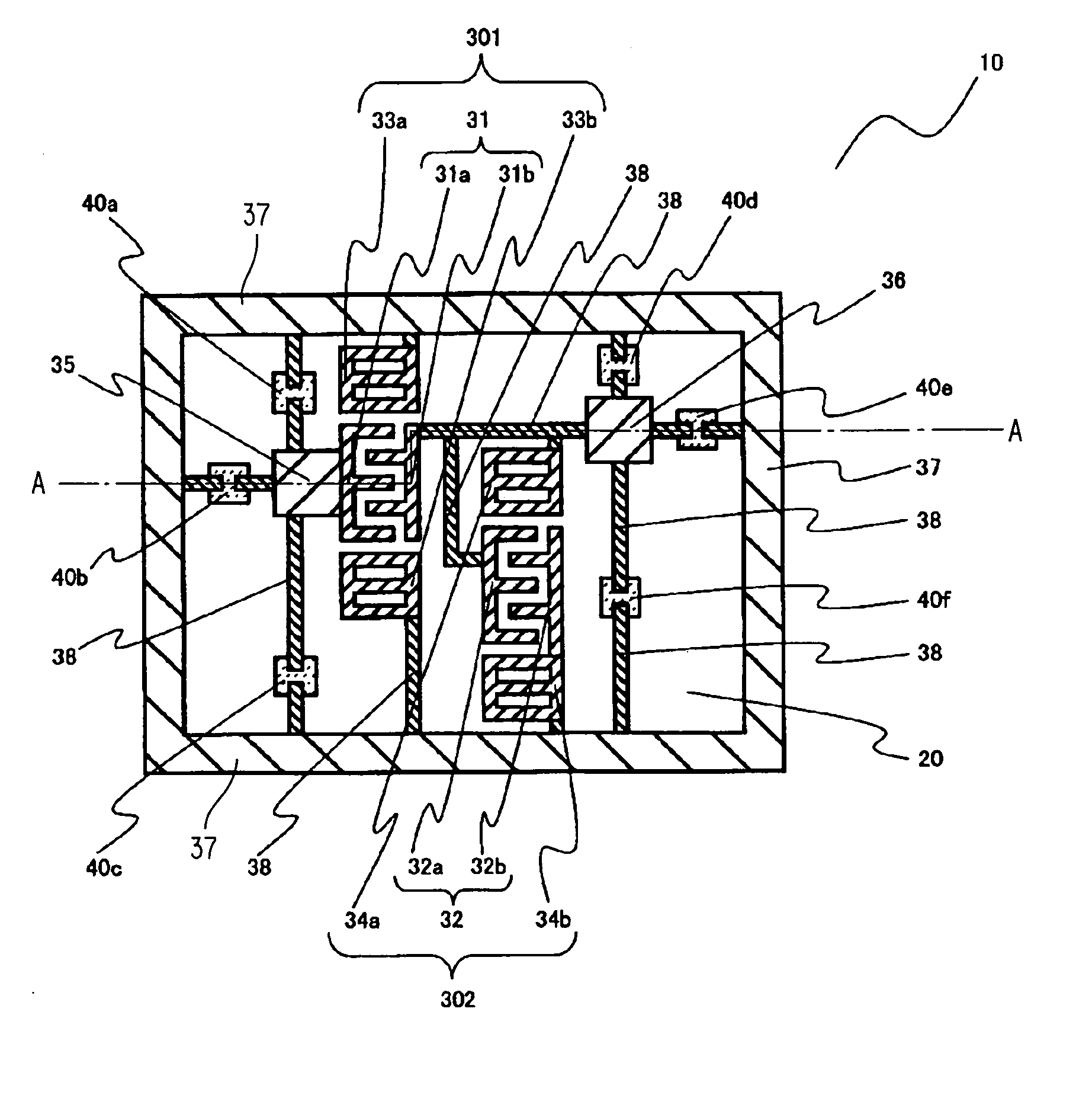
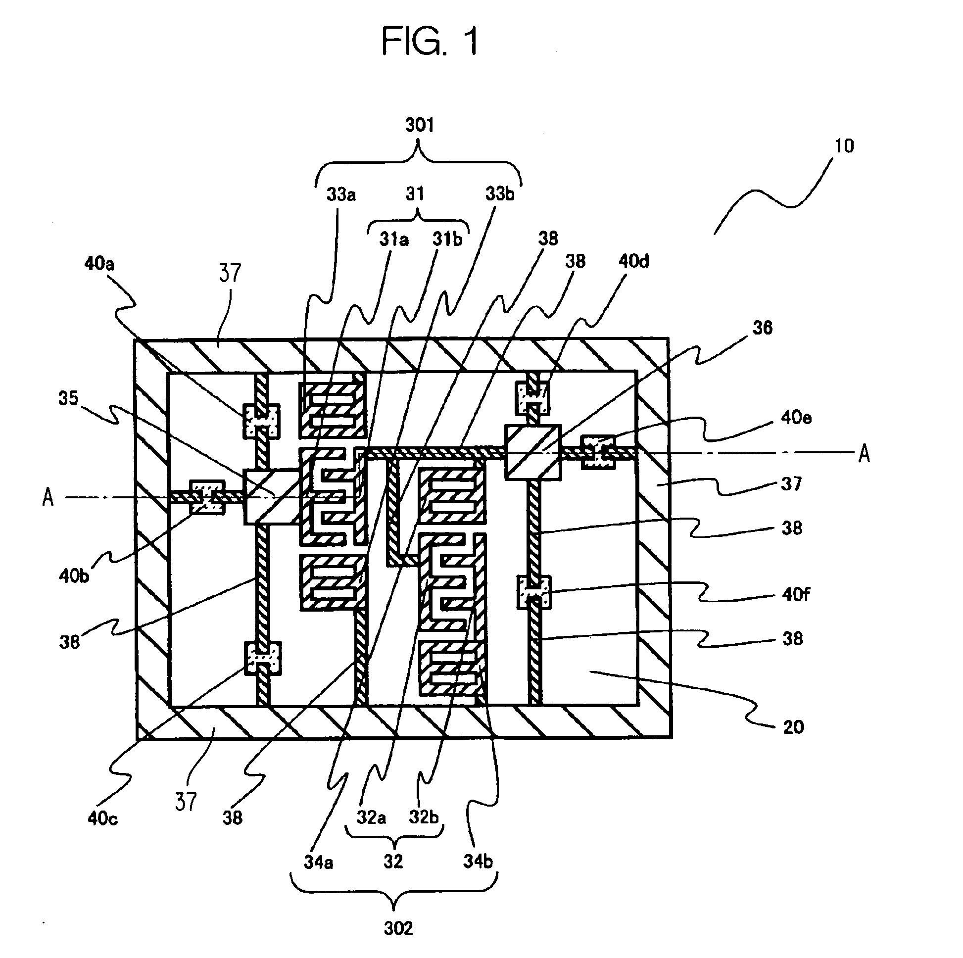
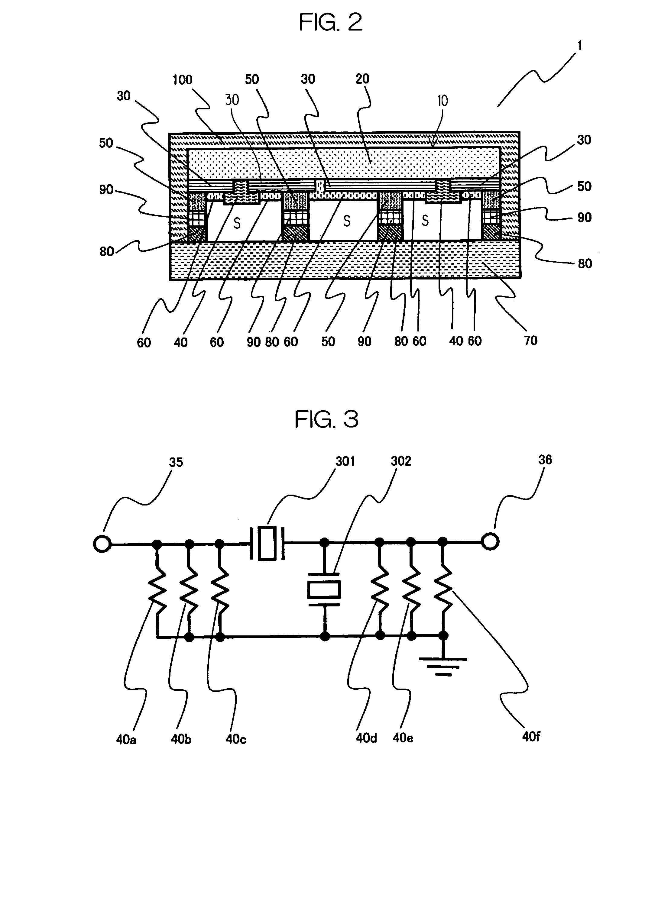
[0020]Because the paired comb-teeth-shaped electrodes forming the IDT electrode are electrically connected to each other via the resistor, charges induced by the pyroelectric effect due to an abrupt change in temperature or the like move through the resistor, which prevents the generation of a potential difference large enough to give rise to a discharge breakdown between the paired comb-teeth-shaped electrodes. It is thus possible to prevent a discharge breakdown in the IDT electrode.
[0038]By adopting the surface acoustic wave apparatus of the invention as a filter, it is possible to provide a compact, highly reliable communications device.

Problems solved by technology

A conventional surface acoustic wave apparatus has a problem that a discharge breakdown occurs in an IDT electrode when exposed to an abrupt change in temperature due to the pyroelectric property of the piezoelectric substrate, which results in deterioration of the electric characteristic.
The conventional surface acoustic wave apparatus described above, however, has the problems as follows.
When the resistor is connected, the electric characteristic of the surface acoustic wave apparatus readily deteriorates.
However, such an elongate resistor readily breaks due to a rise in temperature when a current flows and the resistor generates heats.
When the resistor is heated to approximately 300° C. at the time of reflow soldering and a large current flows through the resistor as charges are induced by the pyroelectric effect, the resistor generates heats and the temperature rises further, which increases the possibility of a break in the resistor per se.
It is thus no longer possible to prevent the occurrence of a discharge breakdown in the IDT electrode caused by a change in temperature.
Also, the material per se of the thin-film resistor has a problem in its heat resistance, and oxidation proceeds rapidly when the temperature rises, which raises a concern with respect to the reliability.

Method used


Image

  • Surface acoustic wave apparatus and communications device
  • Surface acoustic wave apparatus and communications device
  • Surface acoustic wave apparatus and communications device

Examples


example

[0141]An example where the surface acoustic wave apparatus of the invention is fabricated will now be described.

[0142]The fabrication process of the surface acoustic wave element will be described with reference to FIG. 10. A stepper (step and repeater) and an RIE (Reactive Ion Etching) apparatus are used for photolithography in this fabrication.

[0143]The piezoelectric substrate 20 (single crystal of lithium tantalate with Y-cut at 38.7°) is subjected to ultrasonic cleaning with the use of acetone, IPA, etc. to remove organic components. The substrate is then dried fully in a clean oven, after which the electrode film 30 is deposited on one main surface of the piezoelectric substrate 20. For the film deposition of the electrode film 30, a sputtering apparatus is used, and the electrode film 30 made of Al—Cu (1 wt % of Cu) is deposited. The thickness of this electrode film is approximately 2000 Å.

[0144]Also, an electrode film (not shown) is deposited on the other main surface of the ...


PUM


Abstract

In a surface acoustic wave element 10, in which IDT electrodes 31 and 32, a grounding electrode 37, etc. are formed one main surface of a piezoelectric substrate 20, resistors 40 made of a semiconductor are provided to connection electrodes 38 that interconnect the respective electrodes. By forcing the charges generated in the IDT electrodes to move via the resistors 40, it is possible to provide a compact, highly reliable surface acoustic wave apparatus capable of preventing an electrostatic discharge damage in the IDT electrodes.

Description

[0001]This application is based on application No. 2003-089362 filed in Japan, the content of which is incorporated hereinto by reference.BACKGROUND OF THE INVENTION[0002]1. Field of the Invention[0003]The present invention relates to a surface acoustic wave apparatus used in a mobile communications device, such as a mobile phone, a device mounted to a vehicle, a device for medical use, etc., and a communications device using the same, and more particularly to a surface acoustic wave apparatus and a communications device characterized by its structure such that prevents a discharge breakdown in an IDT (Inter Digital Transducer) electrode.[0004]2. Description of the Related Art[0005]A surface acoustic wave apparatus, such as a surface acoustic wave resonator and a surface acoustic wave filter, has been widely used in wireless communications devices of various kinds using a microwave band, devices mounted to a vehicle, devices for medical use, etc.[0006]A conventional surface acoustic...

Claims


Application Information

Patent Timeline
Patent Type & Authority Patents(United States)
IPC IPC(8): H03H9/25H03H3/08H03H9/145H03H9/02H03H9/05H03H9/10
CPCH03H9/02921H03H9/0542H03H9/6483H03H9/1085H03H9/059H01L2224/16225H01L2224/05022H01L2224/05026H01L2224/05571H01L2224/05001H01L2224/05644H01L2924/00014H01L2224/05124H01L2224/05166
Inventor ITO, MOTOKIMAKIBUCHI, DAISUKEYAMAGATA, YOSHIFUMIMARUTA, KOUICHIYOKOTA, YUUKO
Owner KYOCERA CORP
Why Eureka
Try Eureka