
Microfluidic sample delivery devices, systems, and methods

Active Publication Date: 2007-12-04
CAPLIPER LIFE SCI INC
View PDF39 Cites 187 Cited by
  • Summary
  • Abstract
  • Description
  • Claims
  • Application Information

AI Technical Summary

Benefits of technology

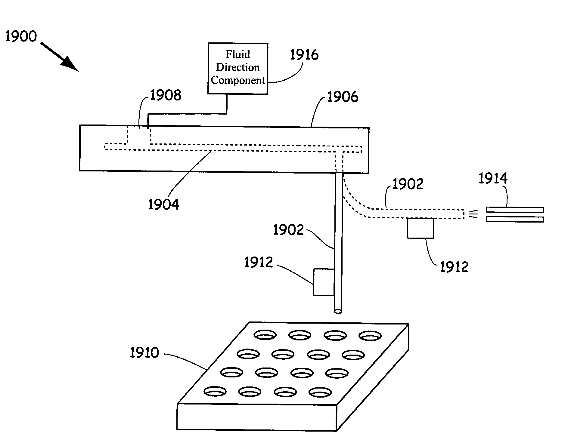
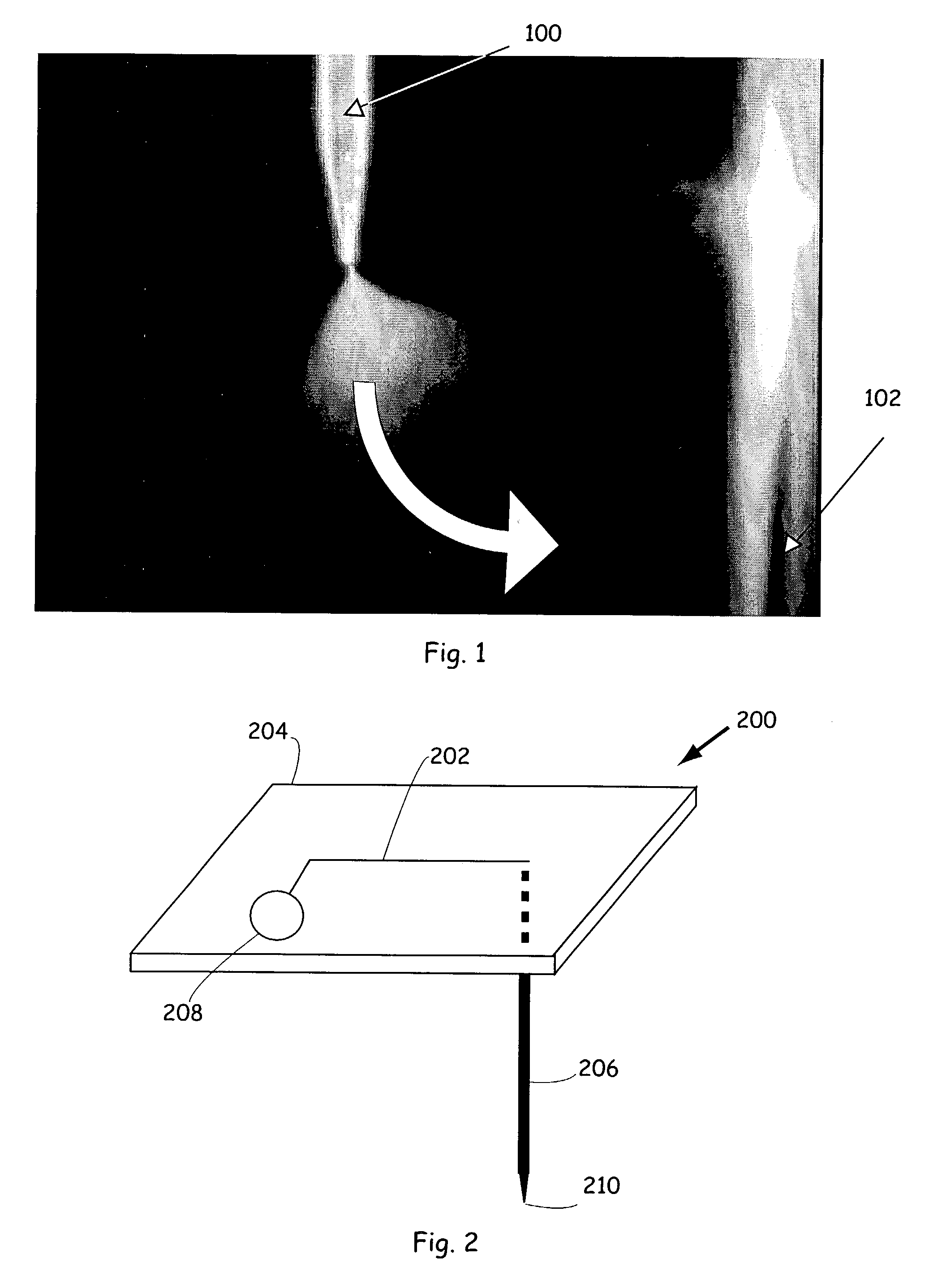
[0008]The present invention generally relates to various microfluidic sample delivery devices and to assorted methods of delivering fluidic sample materials to sample destinations using the devices. In preferred embodiments, fluidic samples are orthogonally electrosprayed from tapered spray tips of capillary elements that extend from the devices of the invention. In certain other embodiments, samples are sprayed from devices that have been rotated from a sample source (e.g., a microwell plate, etc.) to a selected sample destination, such as an orifice of a mass spectrometric detection system. In still other embodiments, capillary elements are flexed, deflected, or otherwise moved between sample sources and sample destinations prior to spraying samples. Various other embodiments are also provided. The highly automated devices, systems, and methods of the invention dramatically increase assay throughput relative to preexisting apparatus and methods of fluid delivery in addition to providing many other significant advantages as described herein.
[0013]In preferred embodiments, the holder includes a microfluidic device. In certain of these embodiments, the method further includes (e) flowing a fluidic material out of the flexible fluid conduit from a cavity of the microfluidic device that fluidly communicates with the flexible fluid conduit to wash the flexible fluid conduit. Optionally, a portion of the fluidic material is flowed to a waste cavity to reduce carryover at a joint between the flexible fluid conduit and a body structure of the microfluidic device. The holder generally includes multiple cavities and the method optionally further includes applying compensating force to fluids in cavities other than the cavity from which the fluidic material is flowed to reduce fluid backflow into the cavities. In certain embodiments, the microfluidic device comprises a plurality of flexible fluid conduits. In some of these embodiments, at least one of (b)-(d) is performed using at least two flexible fluid conduits.

Problems solved by technology

However, the search for lead compounds in the development of new pharmacological agents is frequently impeded by a lack of sufficient assay throughput.
The sources of limited throughput include inadequate methods and devices for delivering sample materials, especially solution-phase samples, to assay detection devices, such as mass spectrometers for analysis.
In particular, many preexisting sample delivery technologies lack sufficient automation to rapidly and reliably accommodate the enormous numbers of compounds in the libraries currently being produced.
Preexisting apparatus and techniques generally lack sufficient automation and throughput to efficiently deliver significant numbers of fluidic samples, such as those produced by combinatorial synthesis, to detection devices for analysis or to other sample destinations.

Method used


Image

  • Microfluidic sample delivery devices, systems, and methods
  • Microfluidic sample delivery devices, systems, and methods
  • Microfluidic sample delivery devices, systems, and methods

Examples


Embodiment Construction

I. Introduction

[0061]The present invention addresses, e.g., a need for apparatus and methods of delivering fluidic sample materials to sample destinations for analysis or processing with sufficient throughput to readily accommodate large compound libraries and assays involving such libraries. In particular, the invention provides microfluidic sample delivery devices and systems capable of rapidly delivering fluidic materials from sample sources, such as microwell plates to, e.g., various detection systems. In preferred embodiments and as emphasized herein for purposes of clarity of illustration, samples are electrosprayed proximal to mass spectrometric inlet system orifices to access the rich information content typically provided by this method of detection. Nonetheless, it will be appreciated by those of skill in the art that the apparatus and methods described herein are readily adaptable to other uses beyond mass spectrometric analysis (MS analysis), including but not limited to...


PUM

PropertyMeasurementUnit
Angleaaaaaaaaaa
Lengthaaaaaaaaaa
Electrical conductoraaaaaaaaaa

Abstract

Methods and apparatus for delivering fluidic materials to sample destinations, including mass spectrometers for analysis are provided. In preferred embodiments, sample aliquots are electrosprayed from tapered spray tips of capillary elements into the orifices of mass spectrometric inlet systems. In certain embodiments, fluidic samples are orthogonally sprayed from capillary elements or other fluid conduits, whereas in other embodiments samples are sprayed after devices are rotated or otherwise translocated from sample sources to sample destinations. In still other embodiments, samples are sprayed from flexed or deflected capillary elements at selected sample destinations.

Description

CROSS-REFERENCES TO RELATED APPLICATIONS[0001]Pursuant to 35 U.S.C. §§ 119 and / or 120, and any other applicable statute or rule, this application claims the benefit of and priority to U.S. Ser. No. 60 / 362,291, filed on Mar. 6, 2002, the disclosure of which is incorporated by reference.COPYRIGHT NOTIFICATION[0002]Pursuant to 37 C.F.R. § 1.71(e), Applicants note that a portion of this disclosure contains material which is subject to copyright protection. The copyright owner has no objection to the facsimile reproduction by anyone of the patent document or patent disclosure, as it appears in the Patent and Trademark Office patent file or records, but otherwise reserves all copyright rights whatsoever.FIELD OF THE INVENTION[0003]The present invention relates to sample delivery utilizing microfluidic devices or systems. More specifically, the invention provides improved techniques and apparatus for delivering fluidic materials to detection systems, including mass spectrometers for analys...

Claims


Application Information

Patent Timeline
IPC IPC(8): B01L3/02B32B27/04B32B27/12B32B5/02G01N15/06
CPCG01N30/6095G01N30/84H01J49/167B01L3/502715B01L3/0268Y10T436/25B01L3/565B01L2200/027B01L2200/12B01L2300/0816B01L2300/0838B01L2300/0864B01L2300/0867B01L2400/027B01L2400/0415B01L2400/0487G01N35/1095G01N2030/847G01N2030/8488G01N2035/1039Y10T436/118339Y10T436/11Y10T436/119163Y10T436/2575
Inventor DUBROW, ROBERT S.GREENSTEIN, MICHAELBOUSSE, LUC J.GANDHI, KHUSHROO
Owner CAPLIPER LIFE SCI INC
Learn More